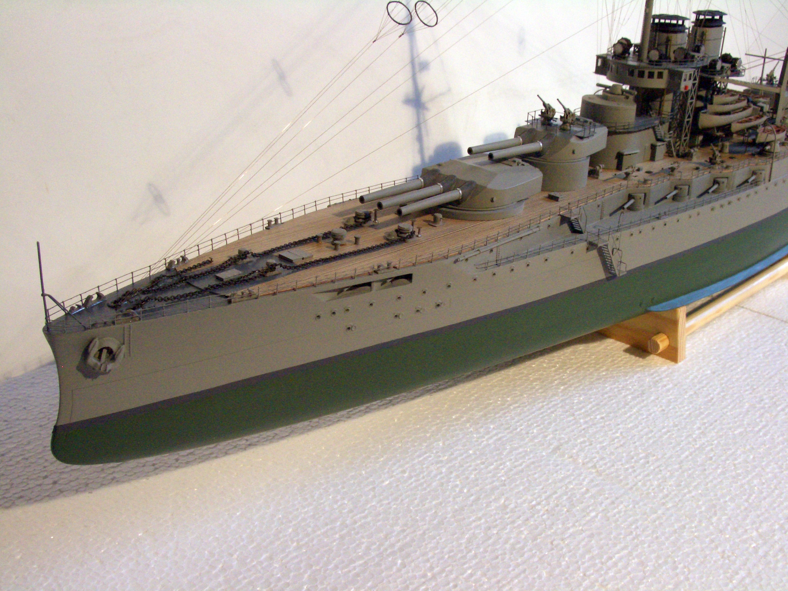
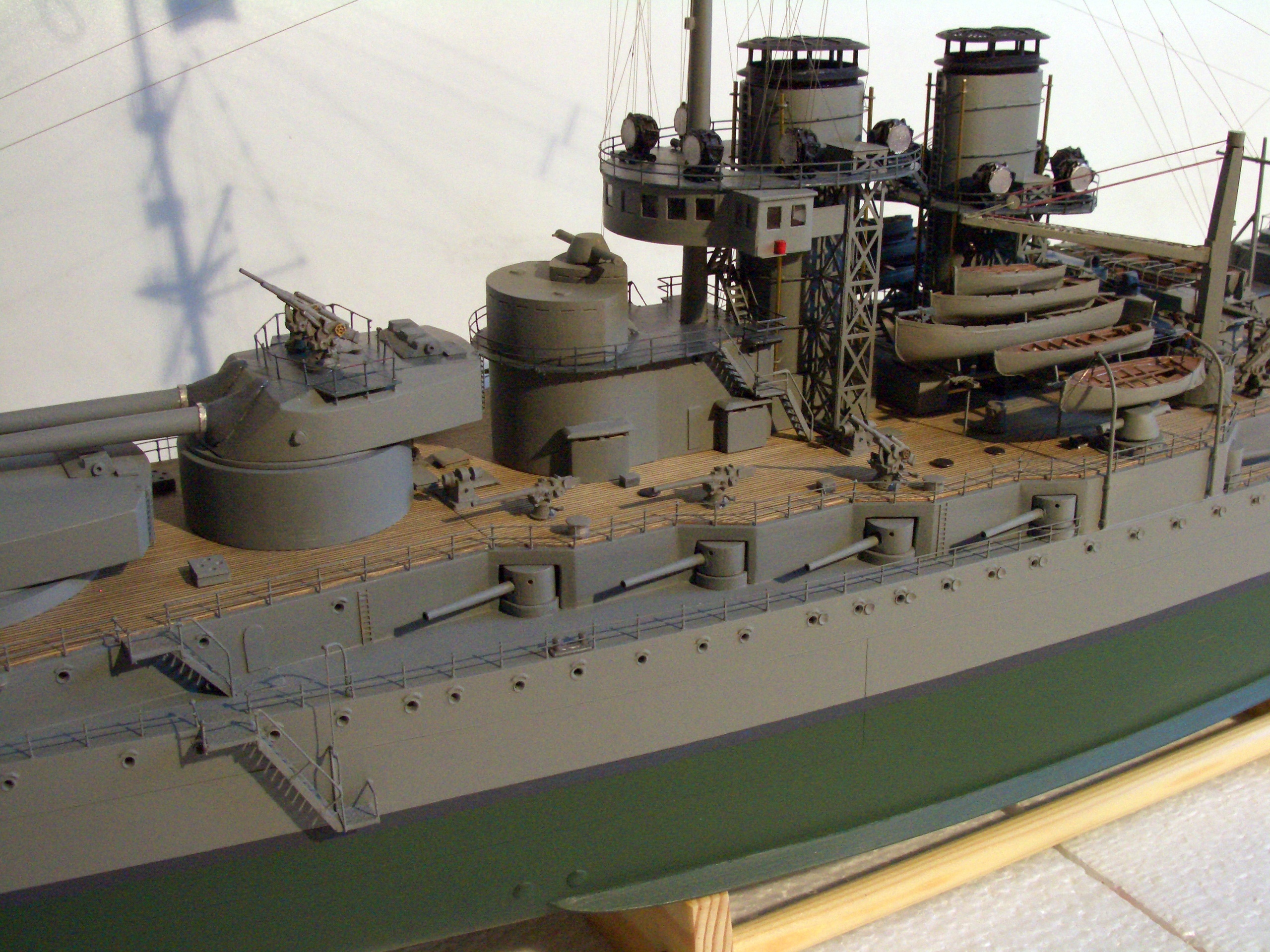
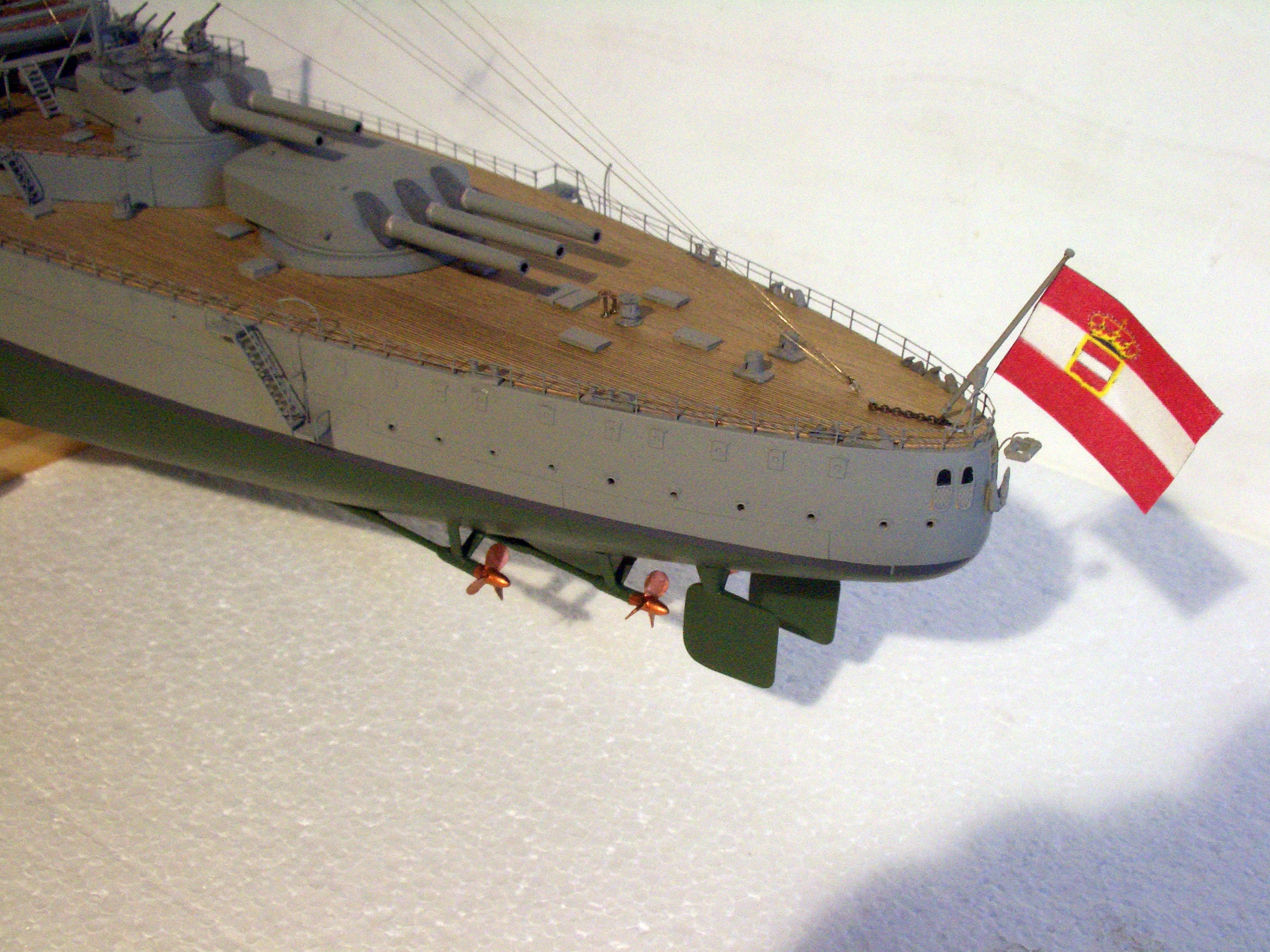
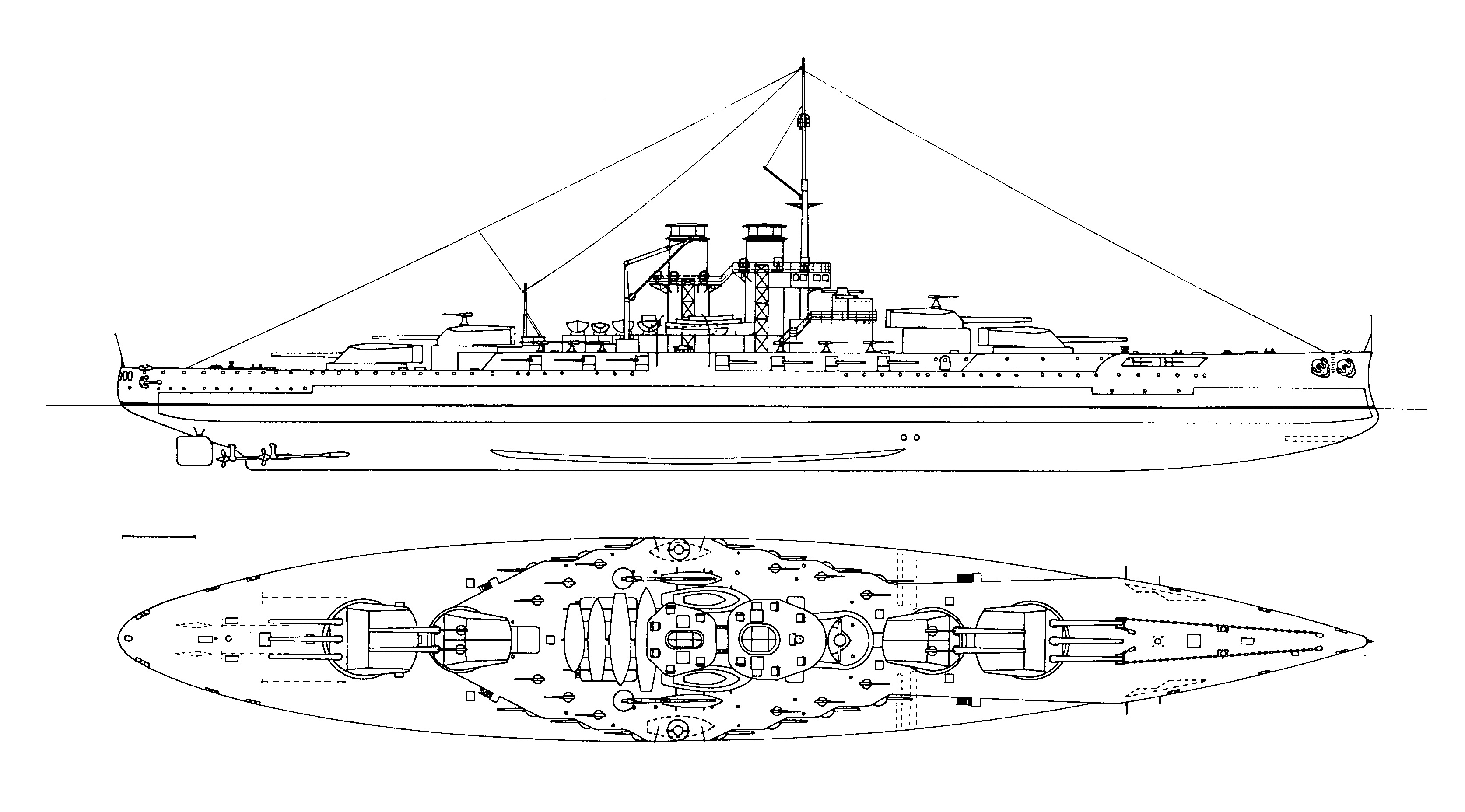
Improved Tegetthoff Class (Ersatz Monarch)
Above:
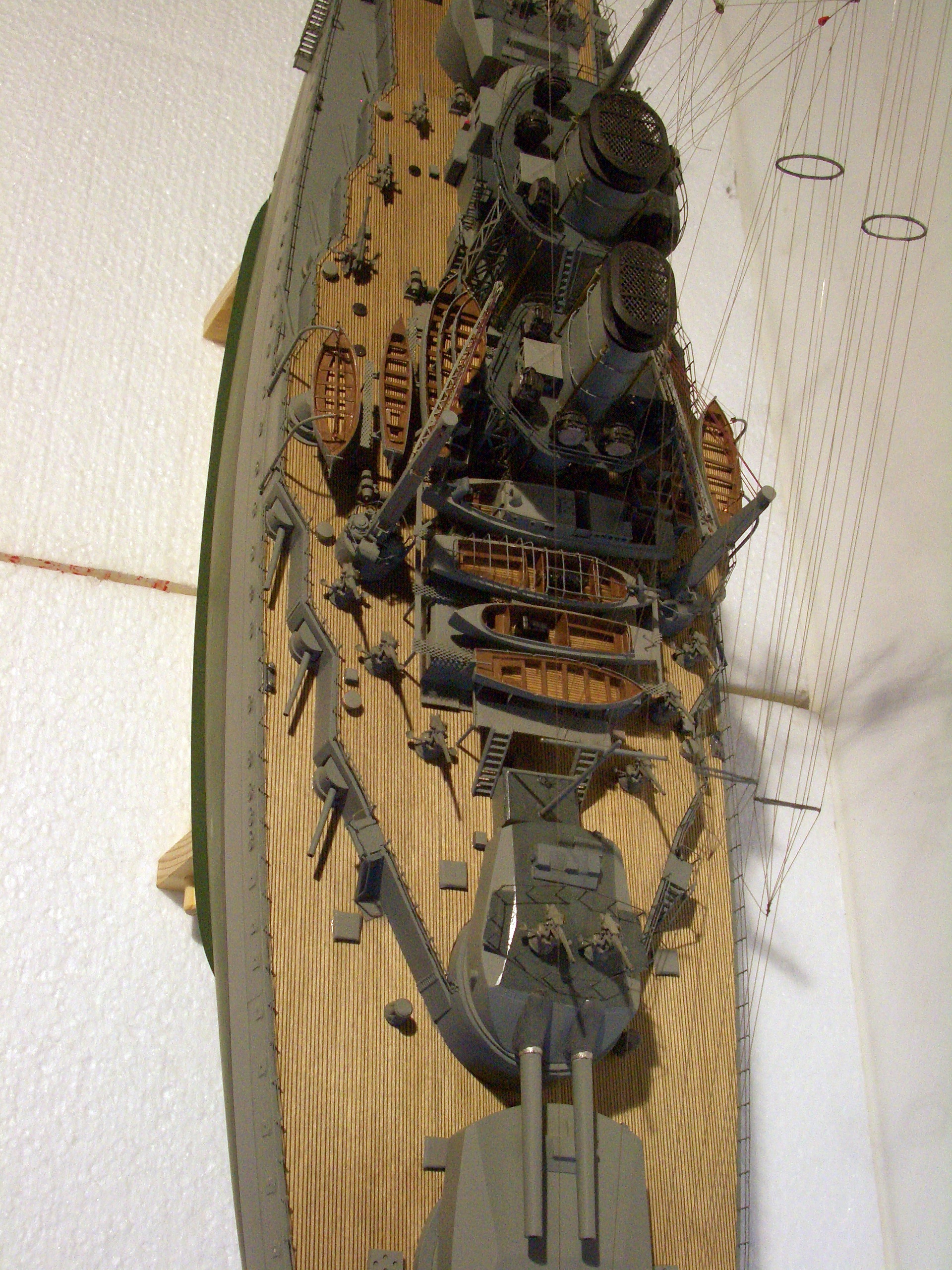
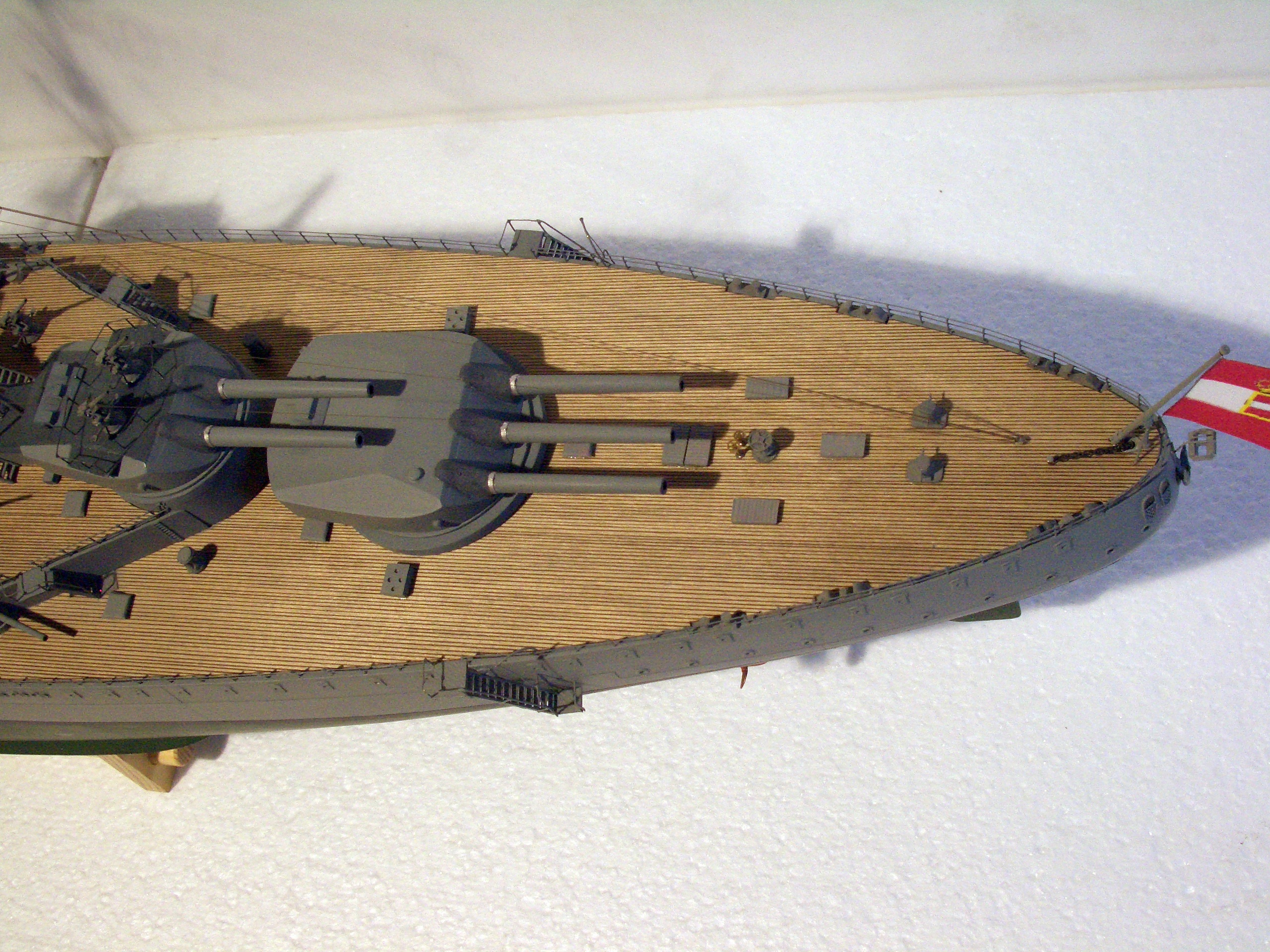
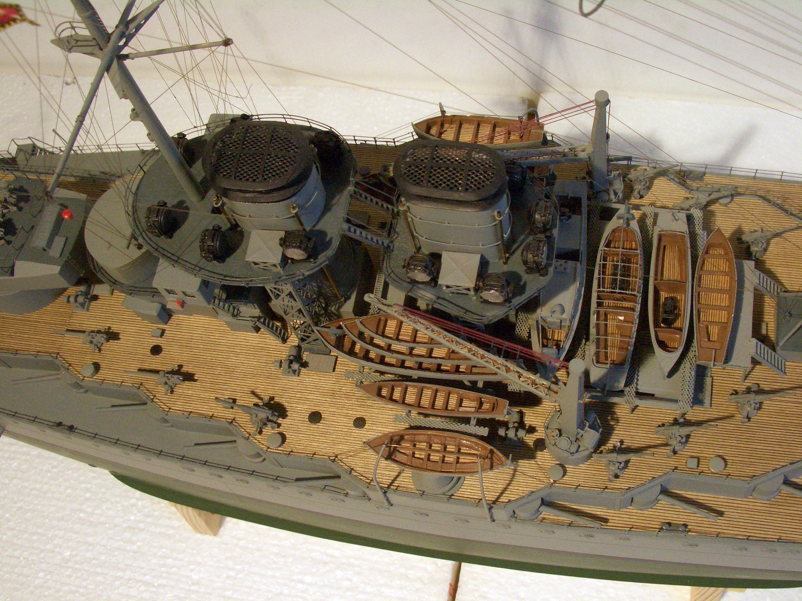
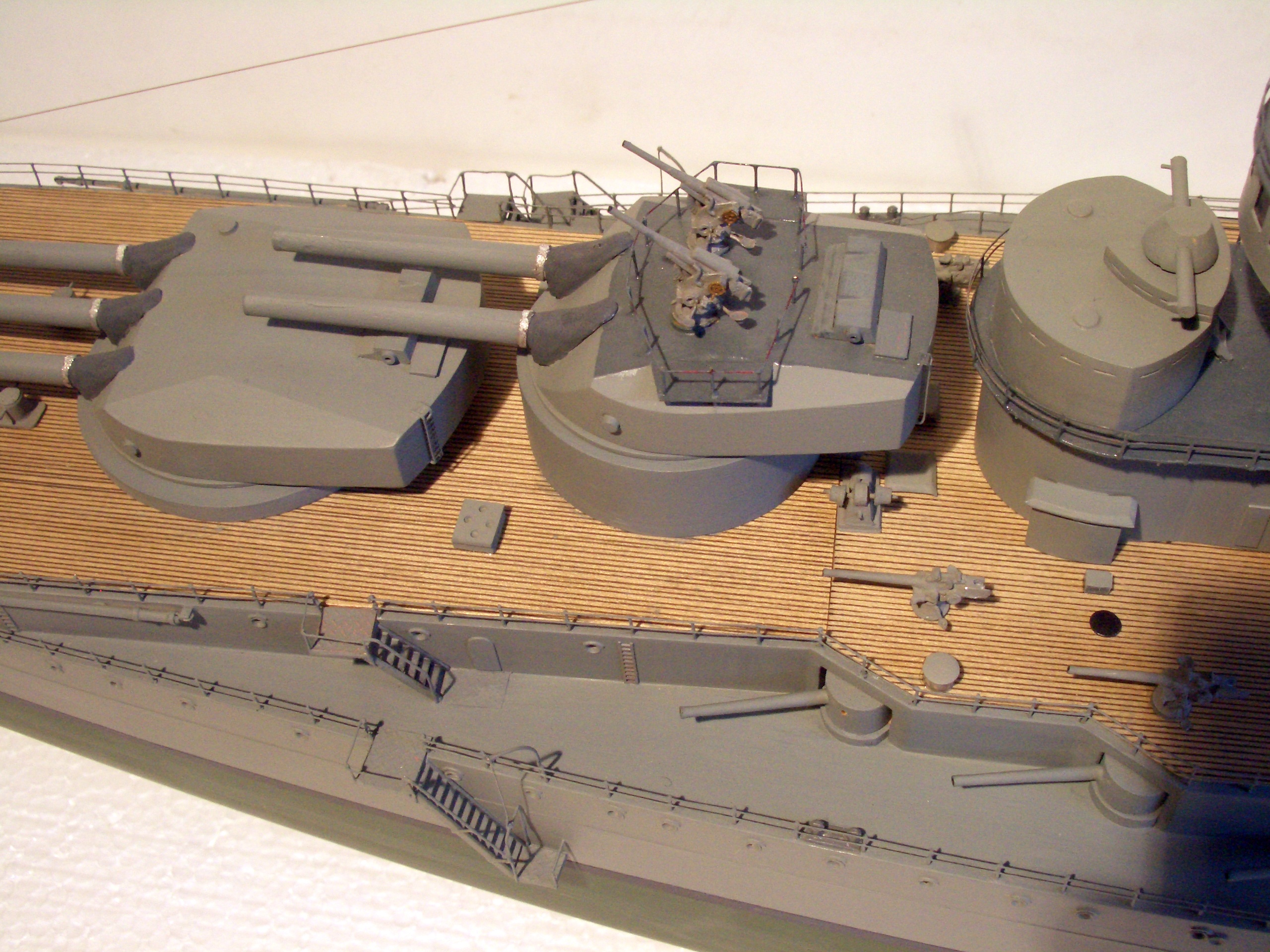
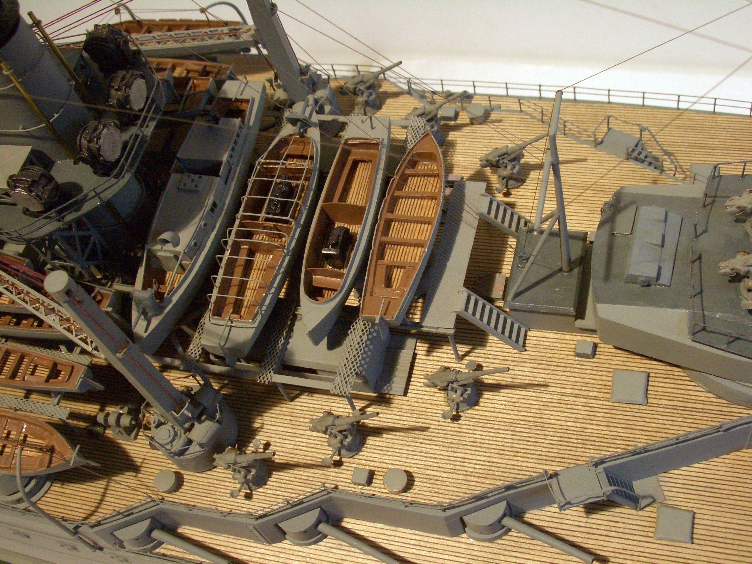
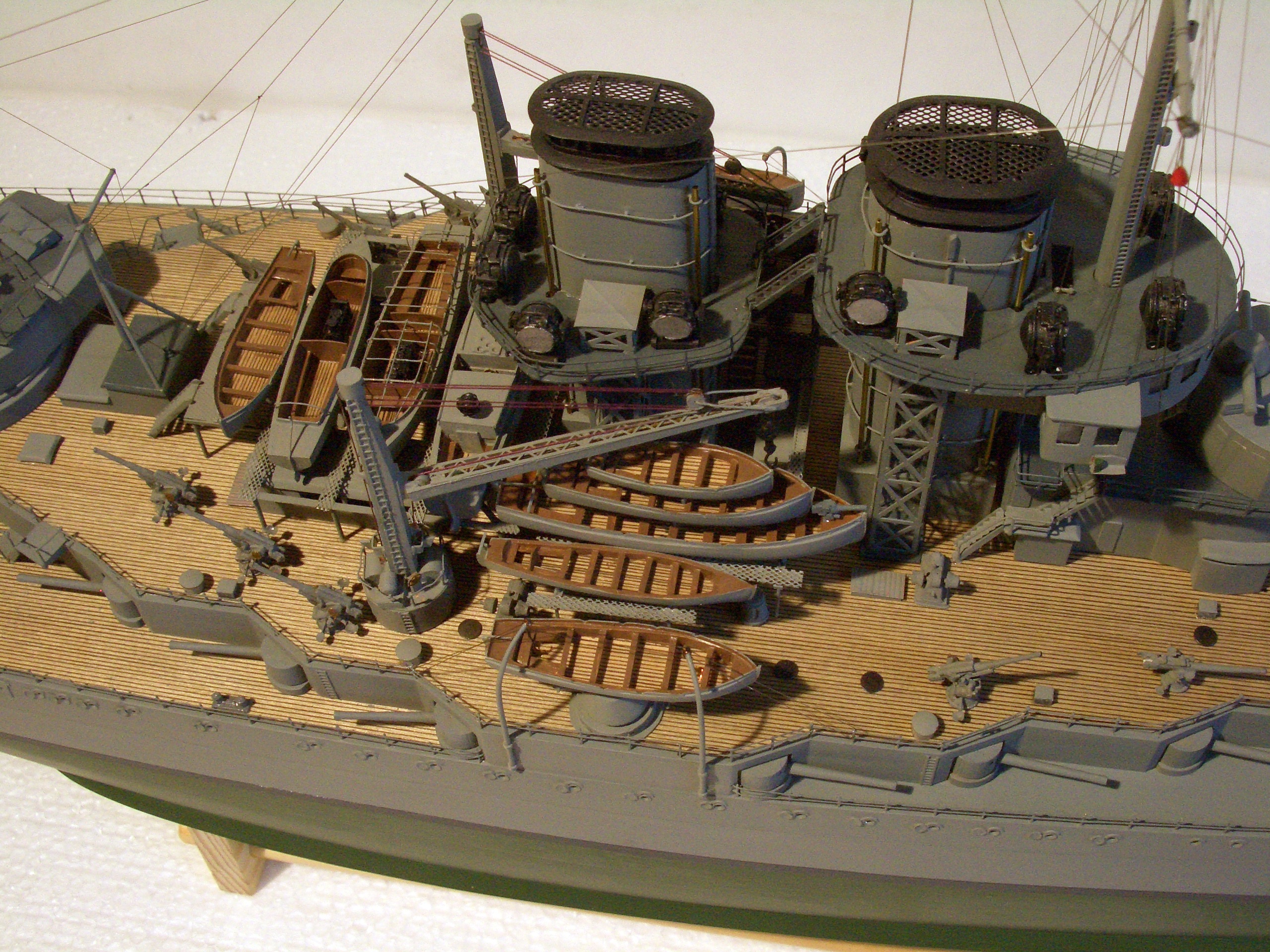
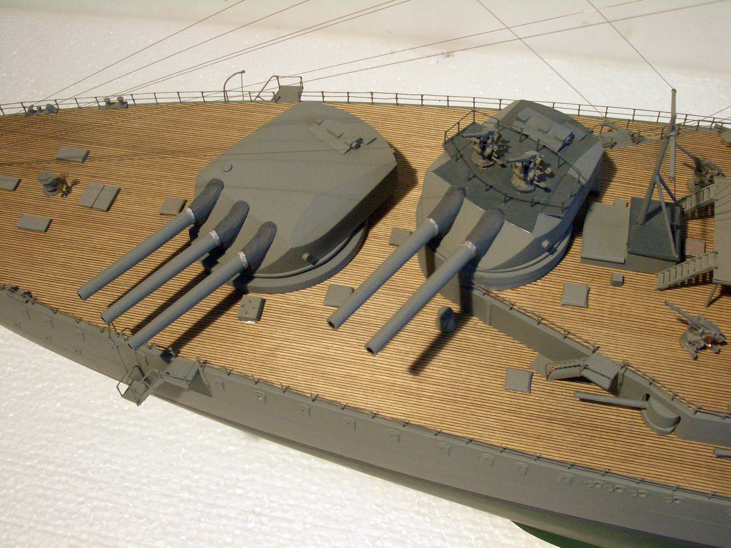
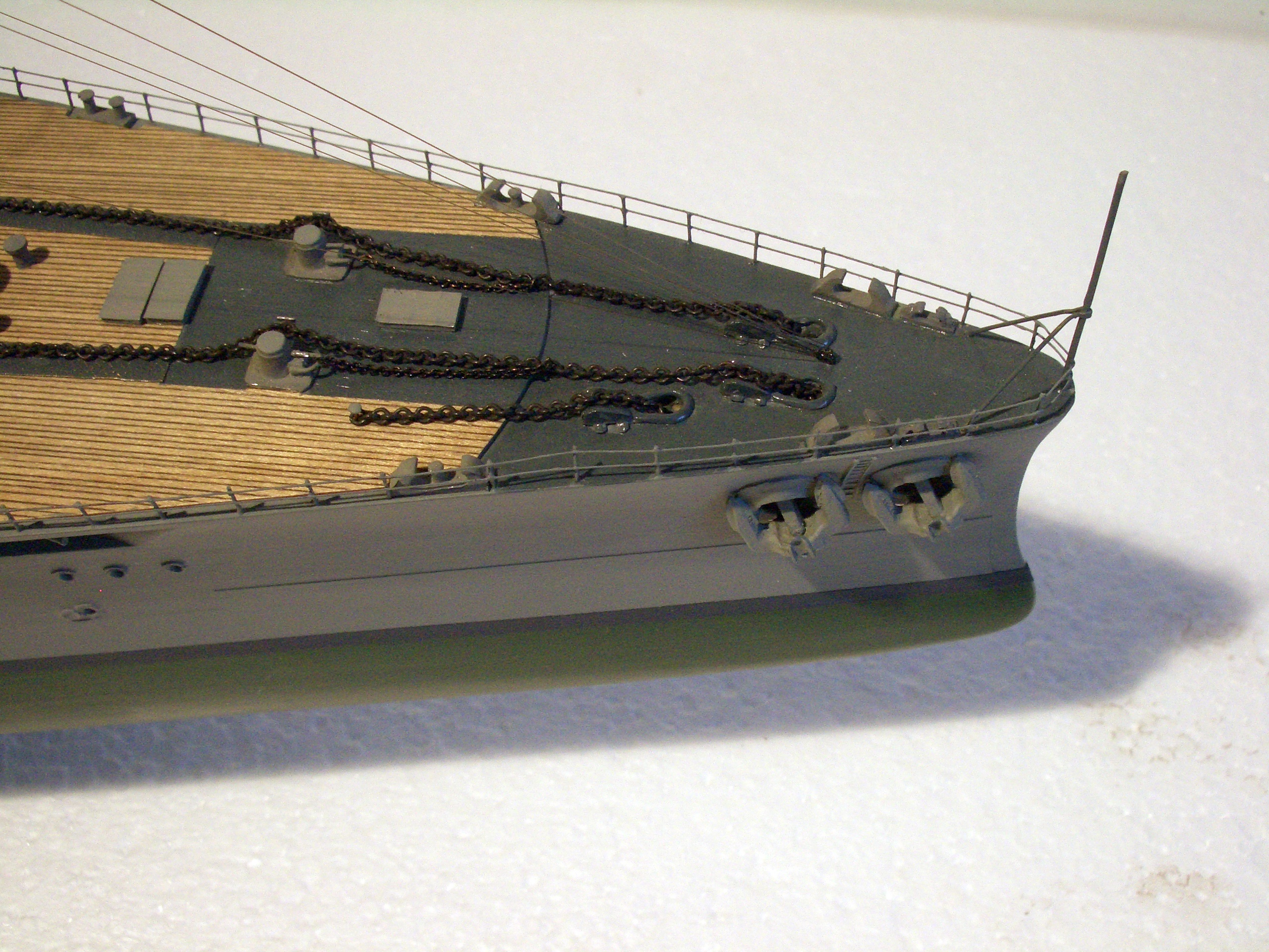
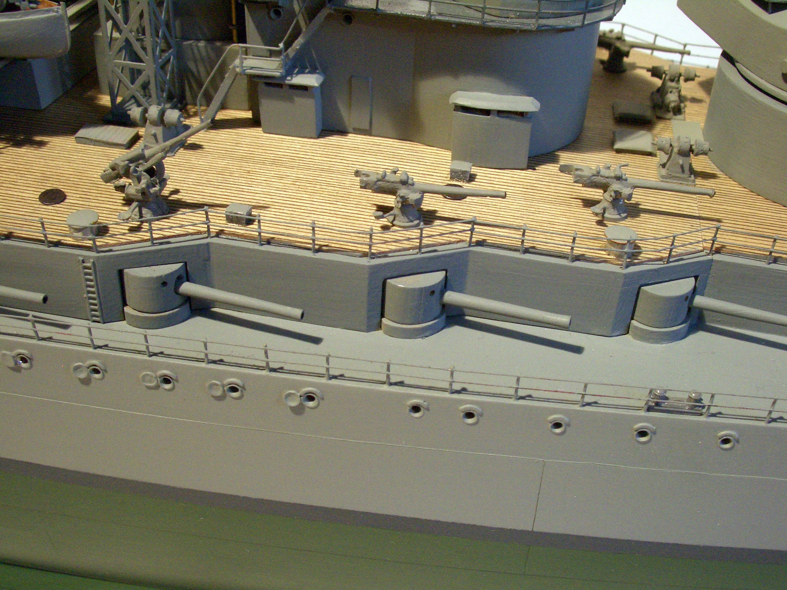
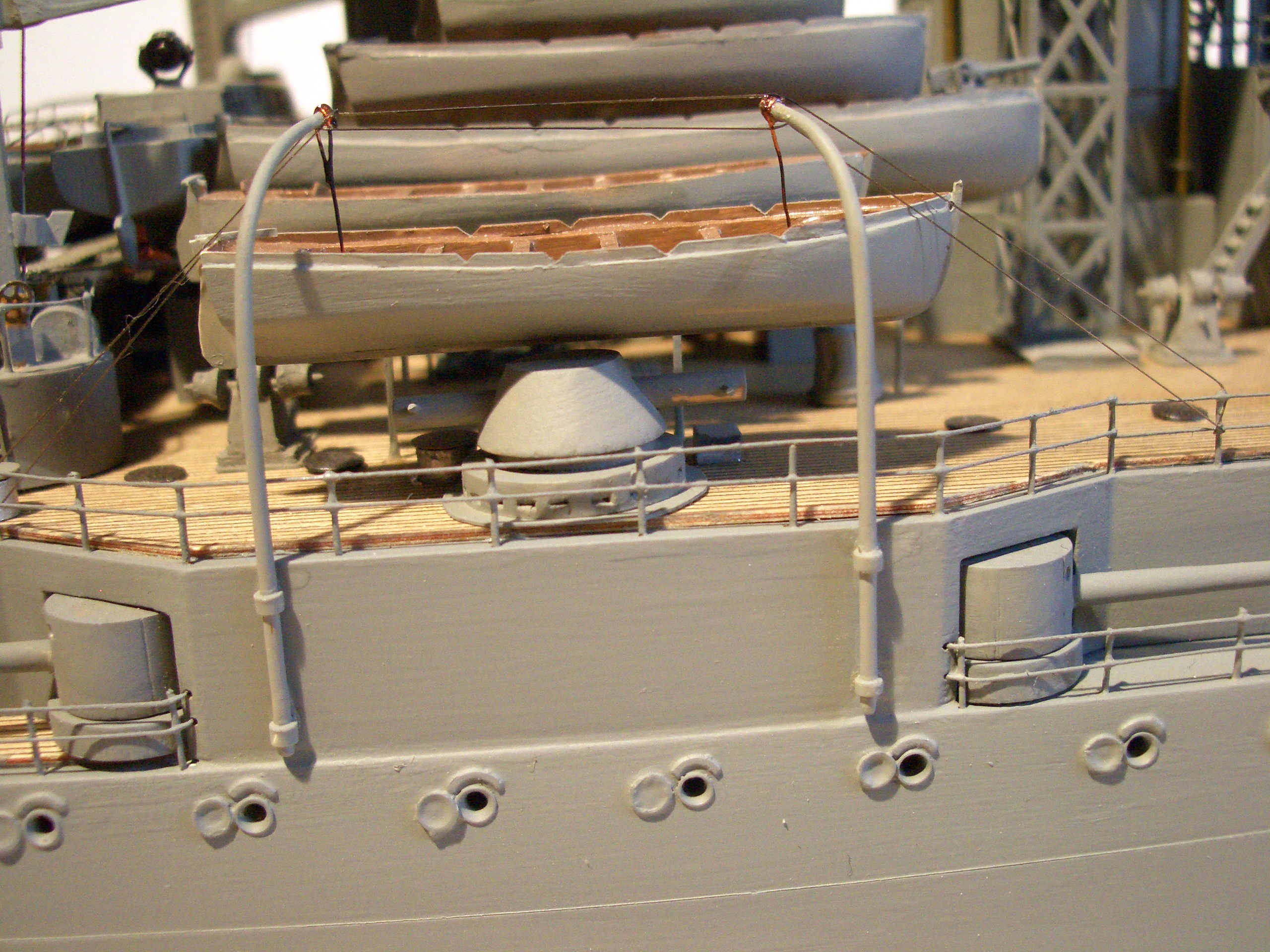
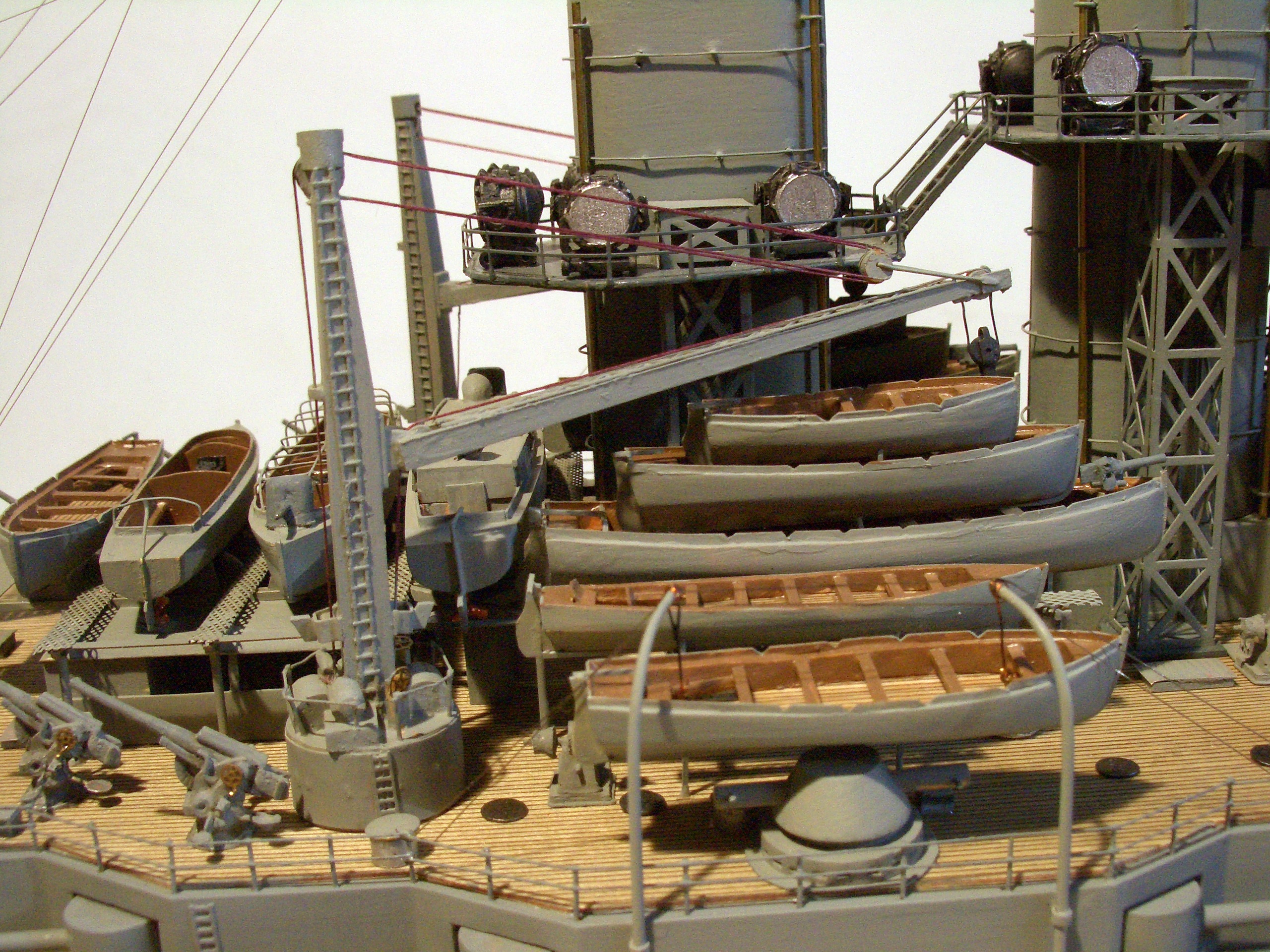
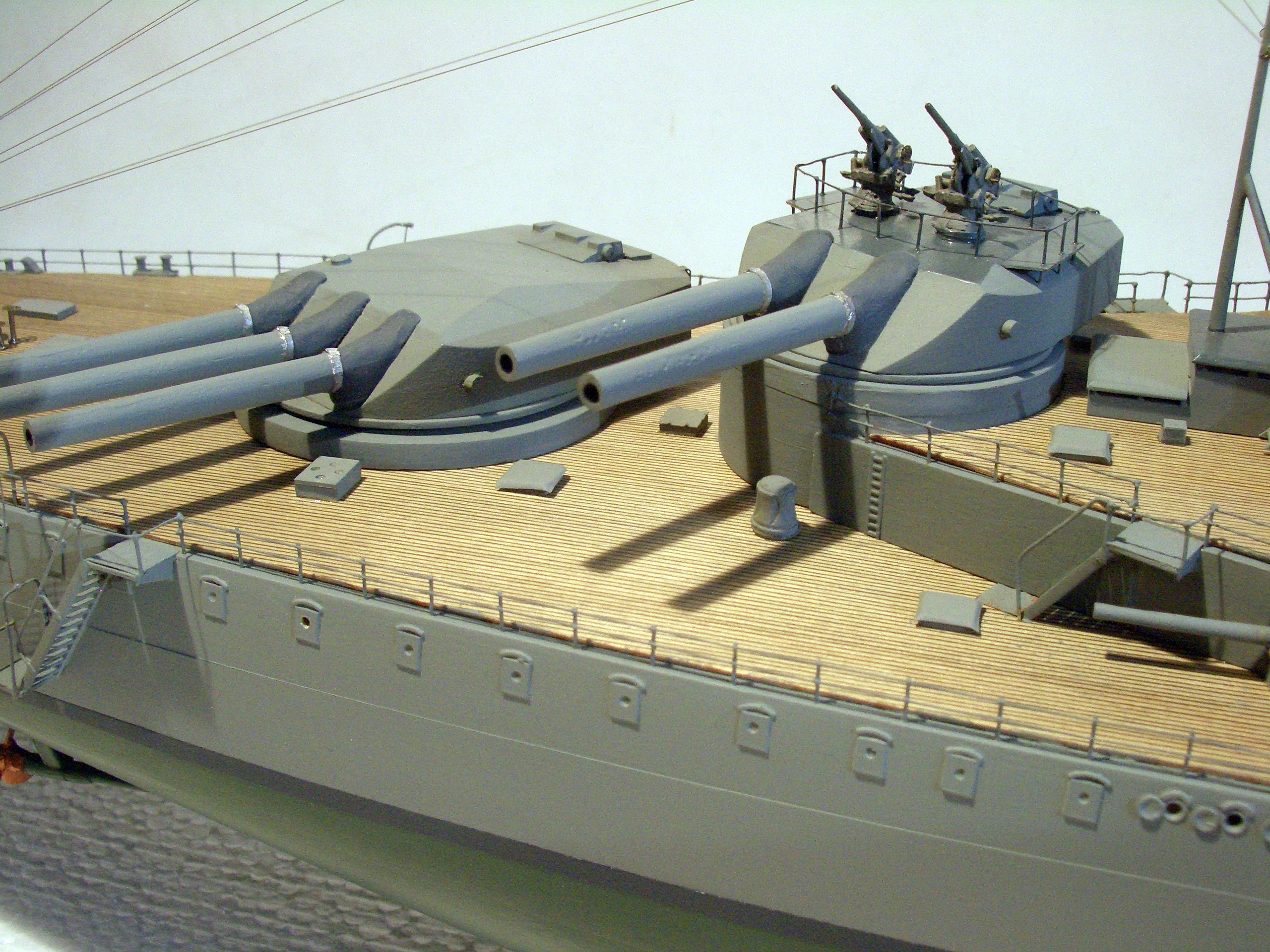
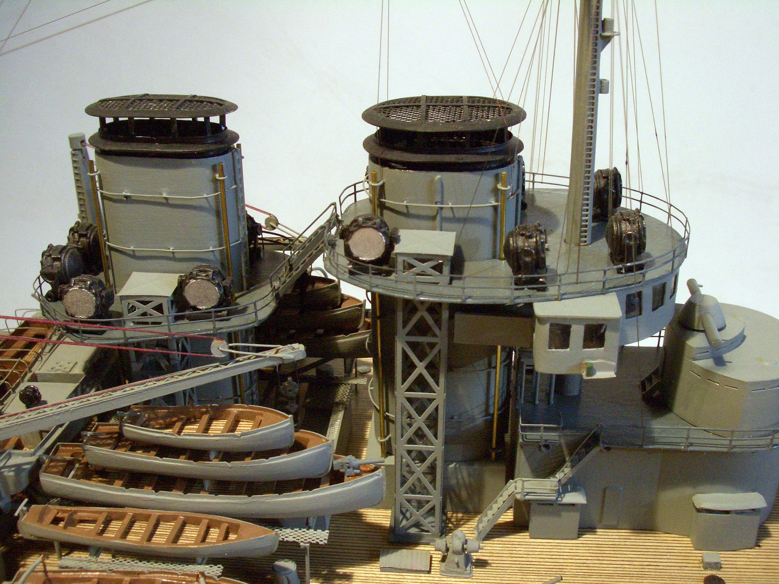
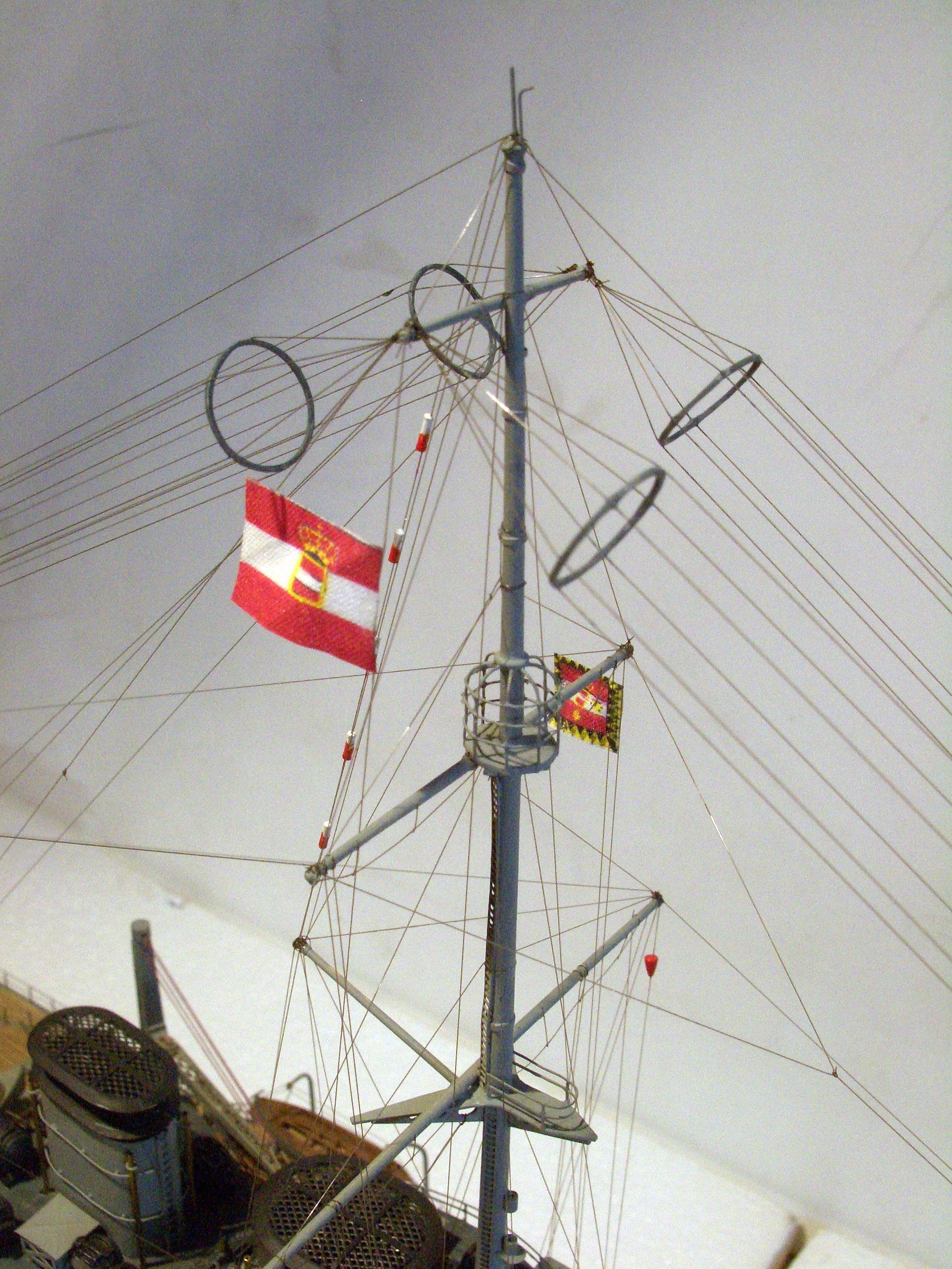
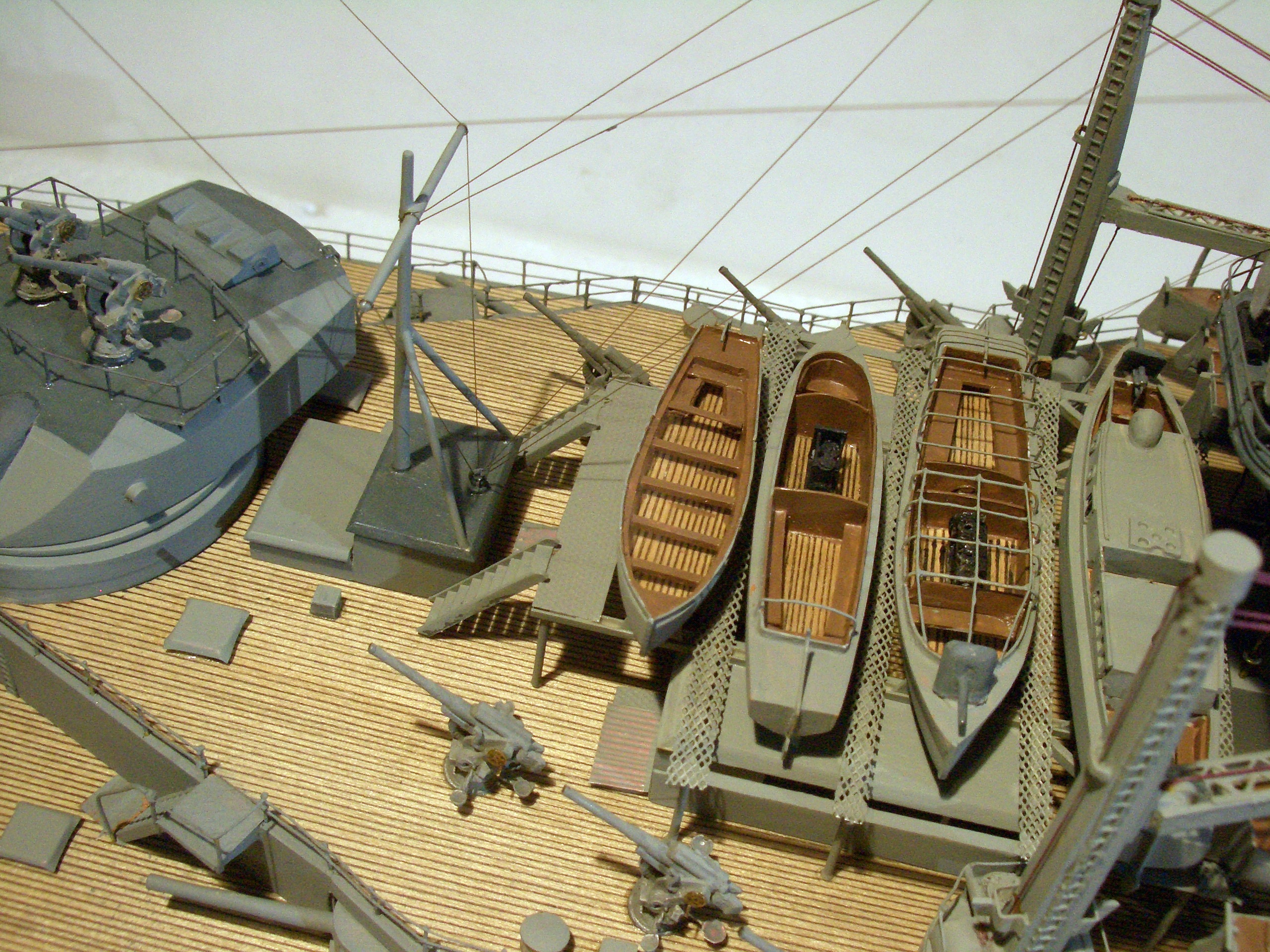
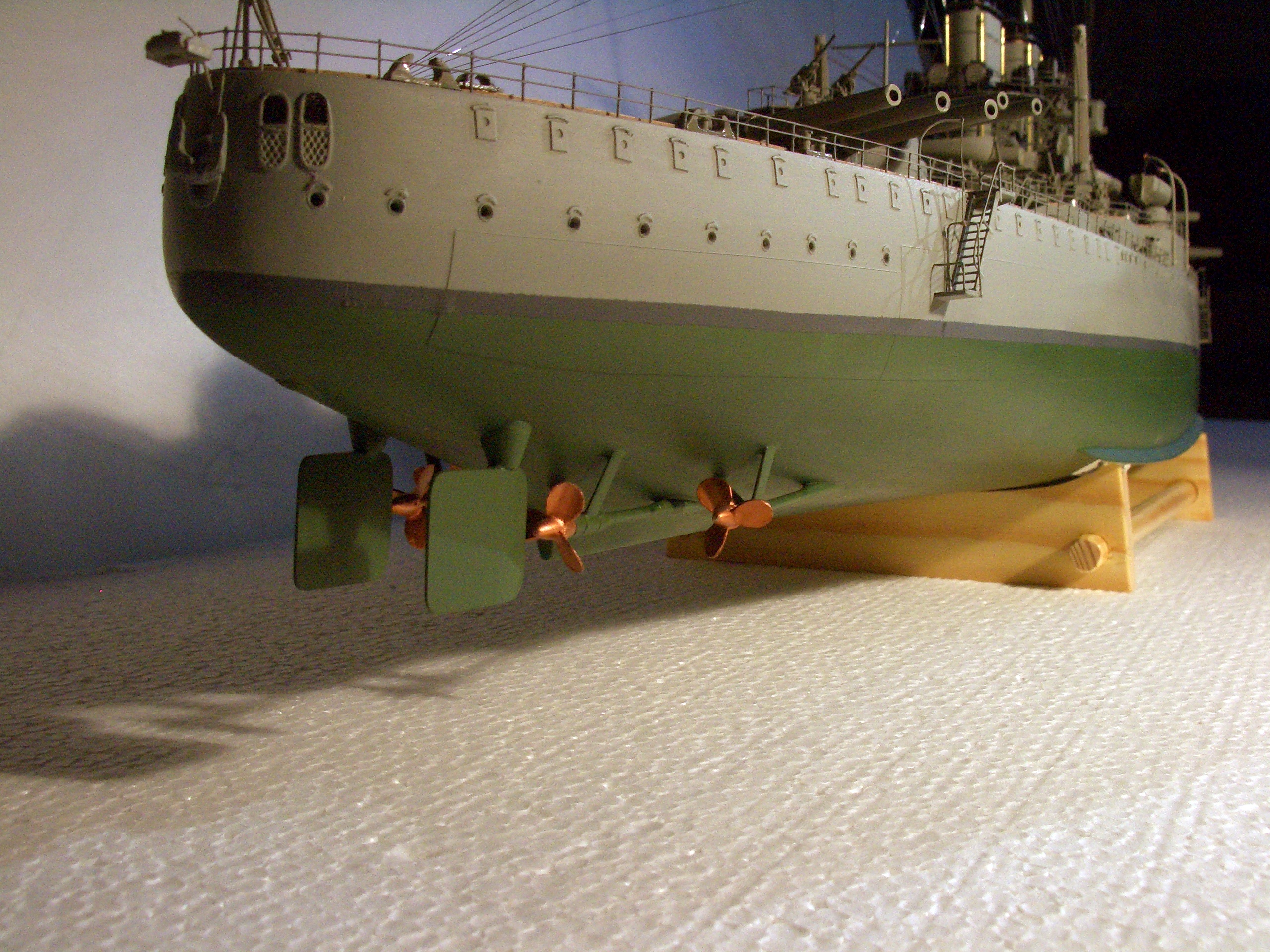
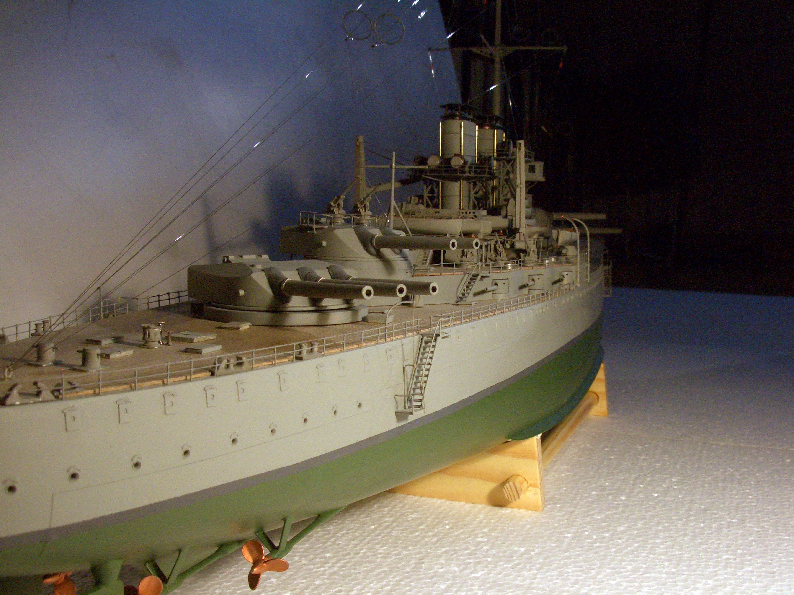
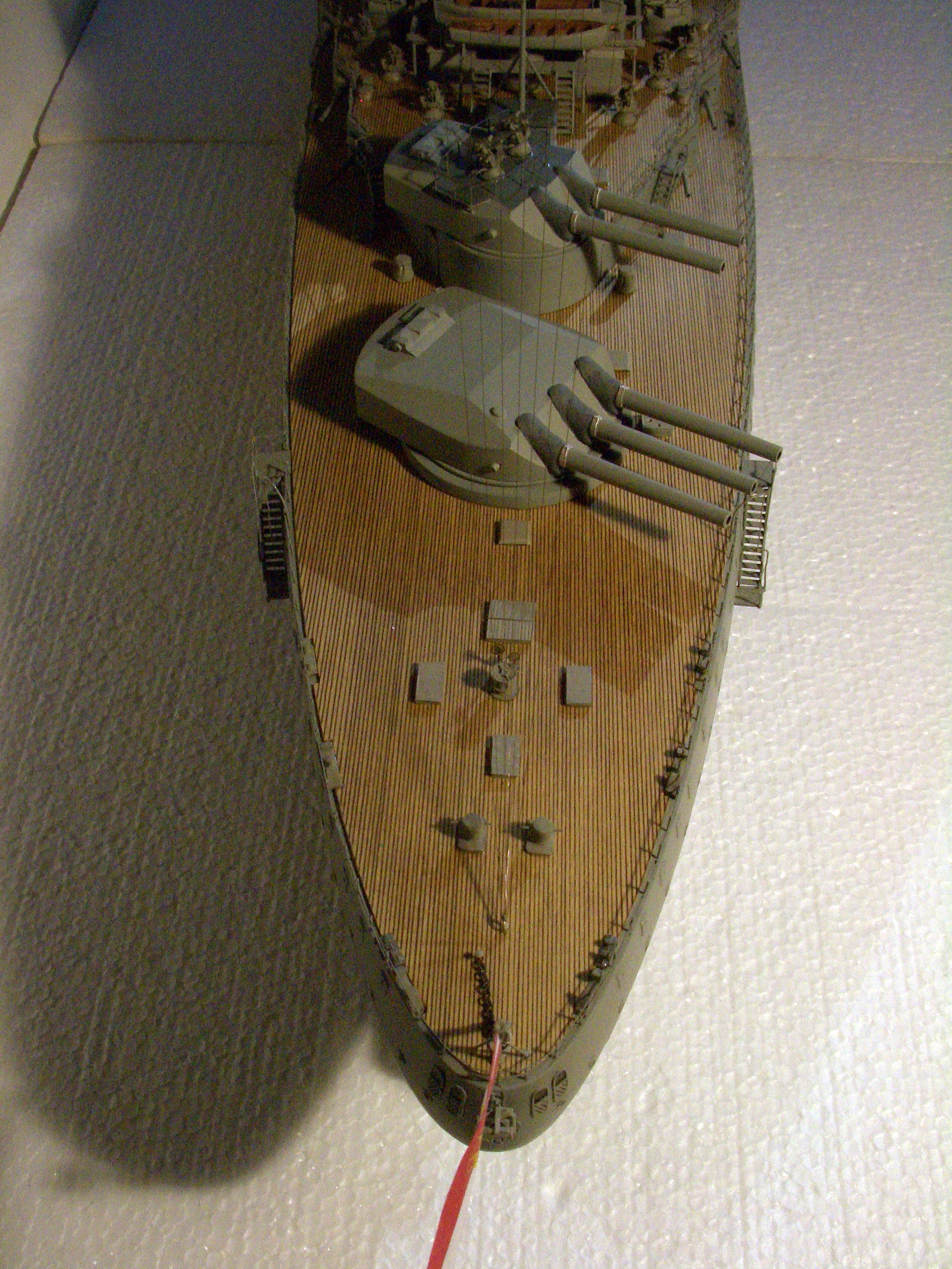
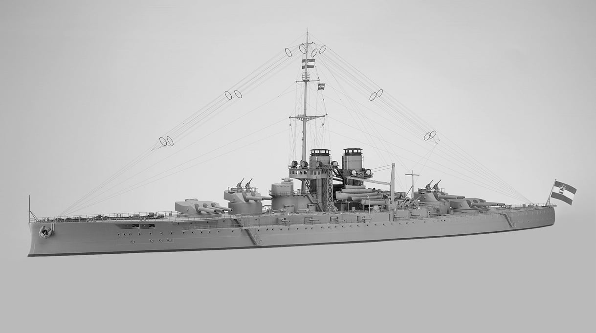
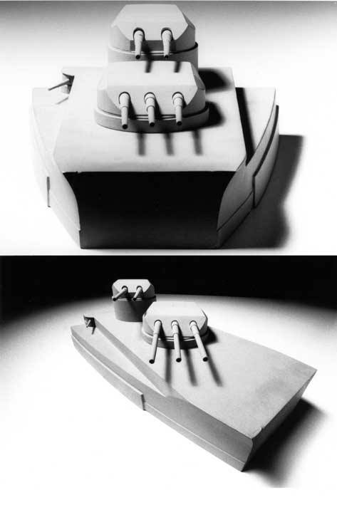
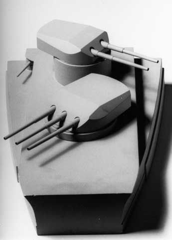
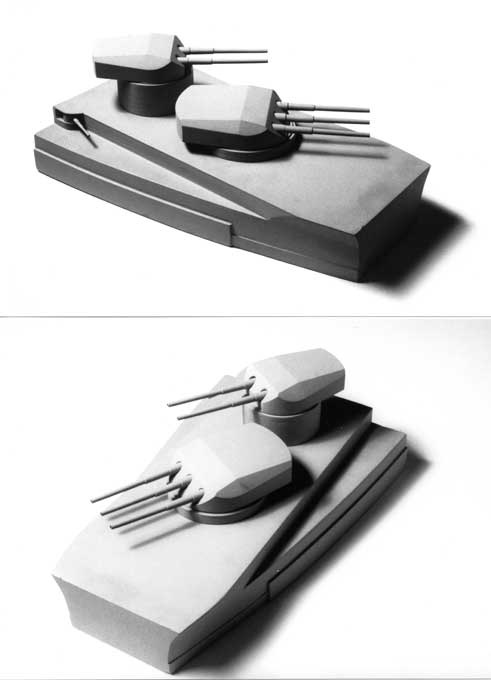
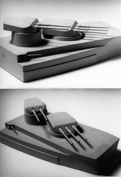
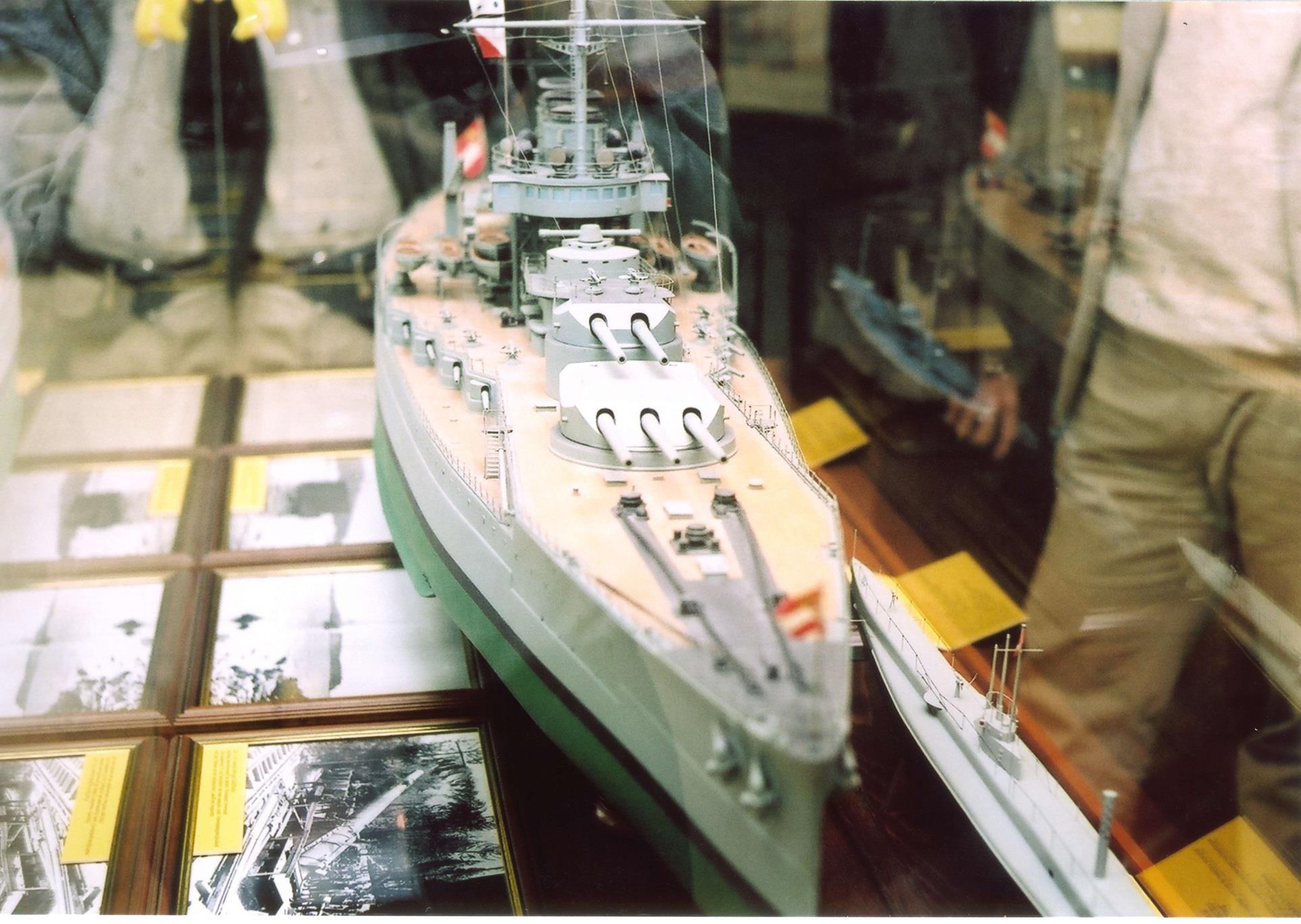
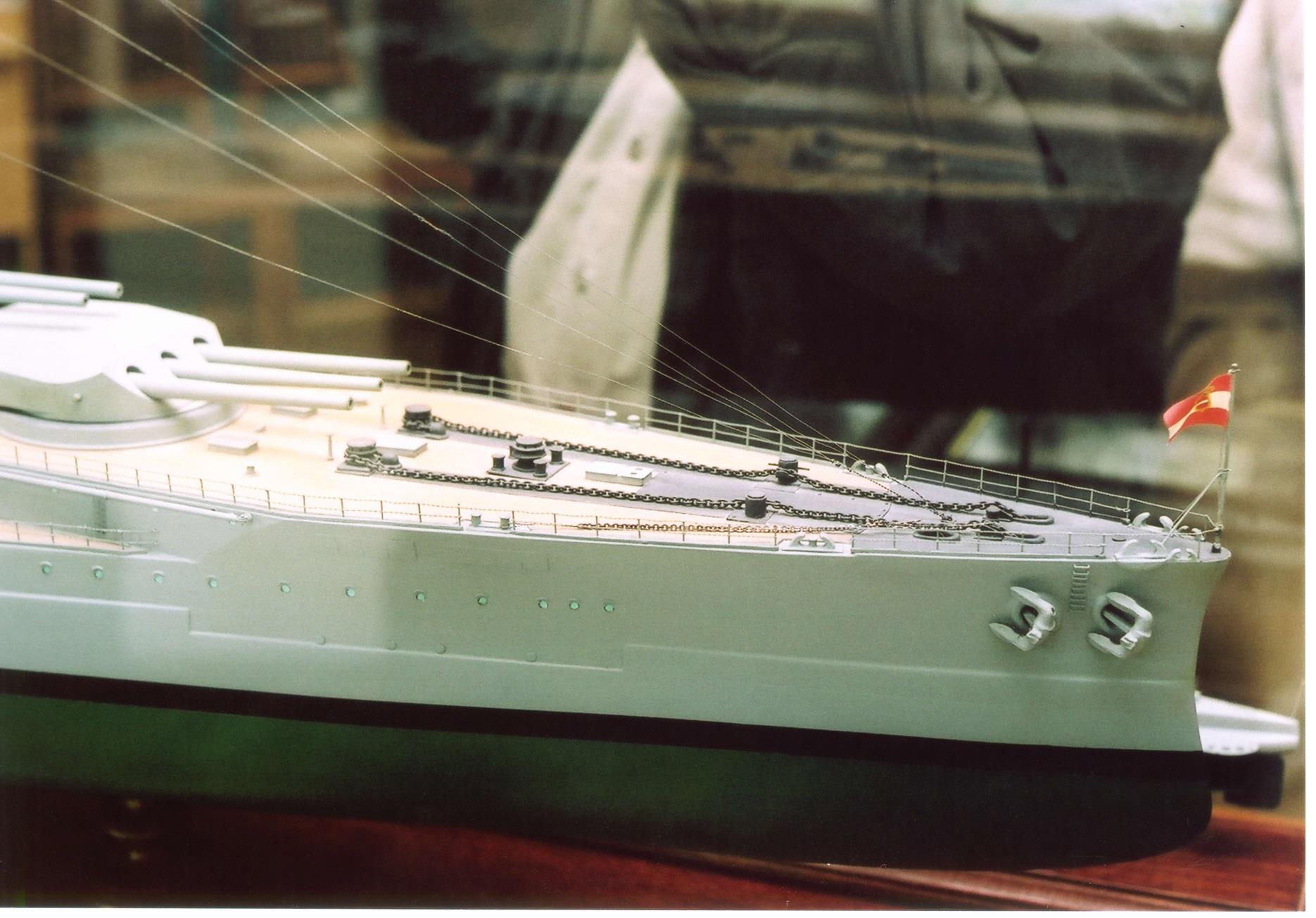
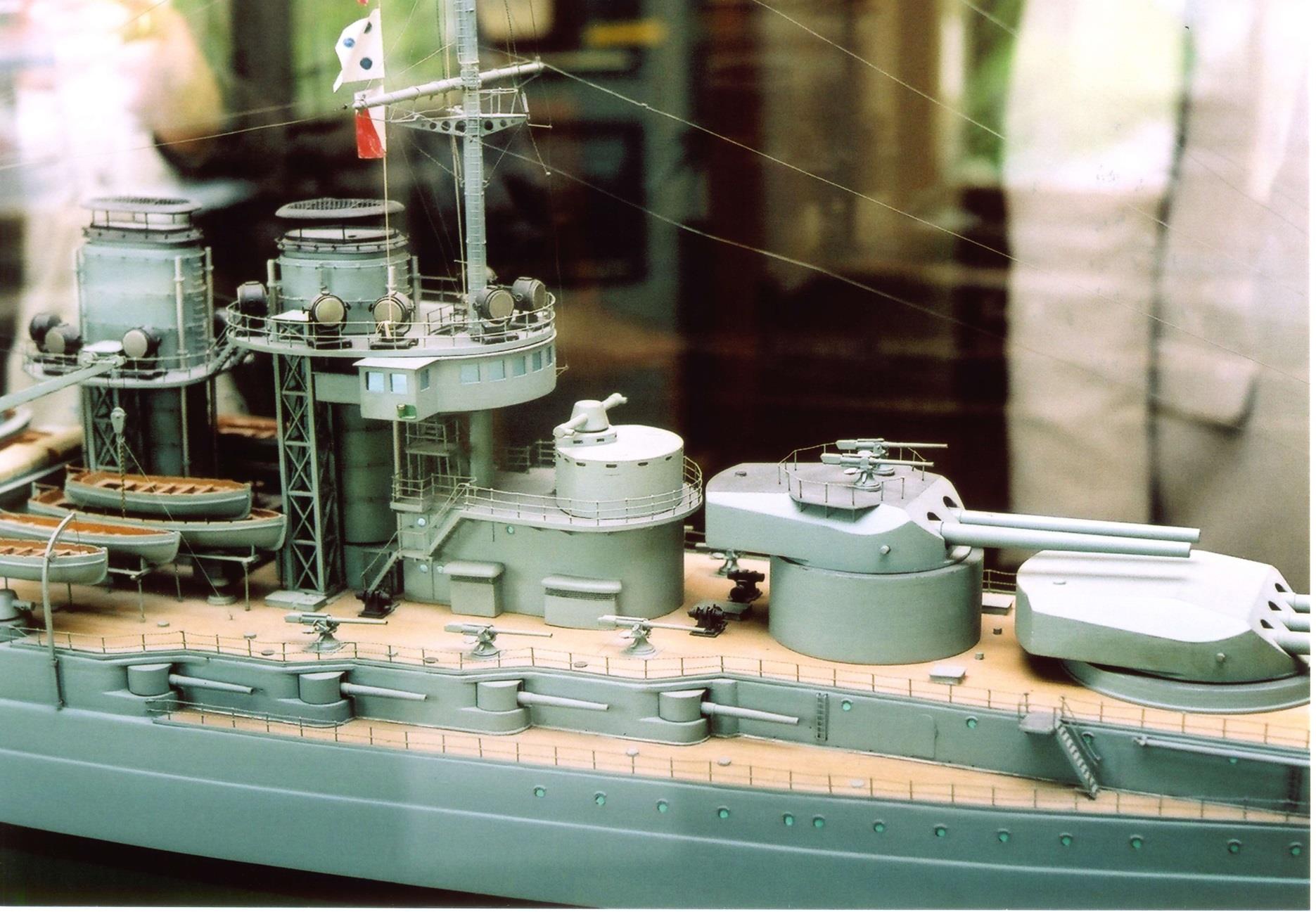
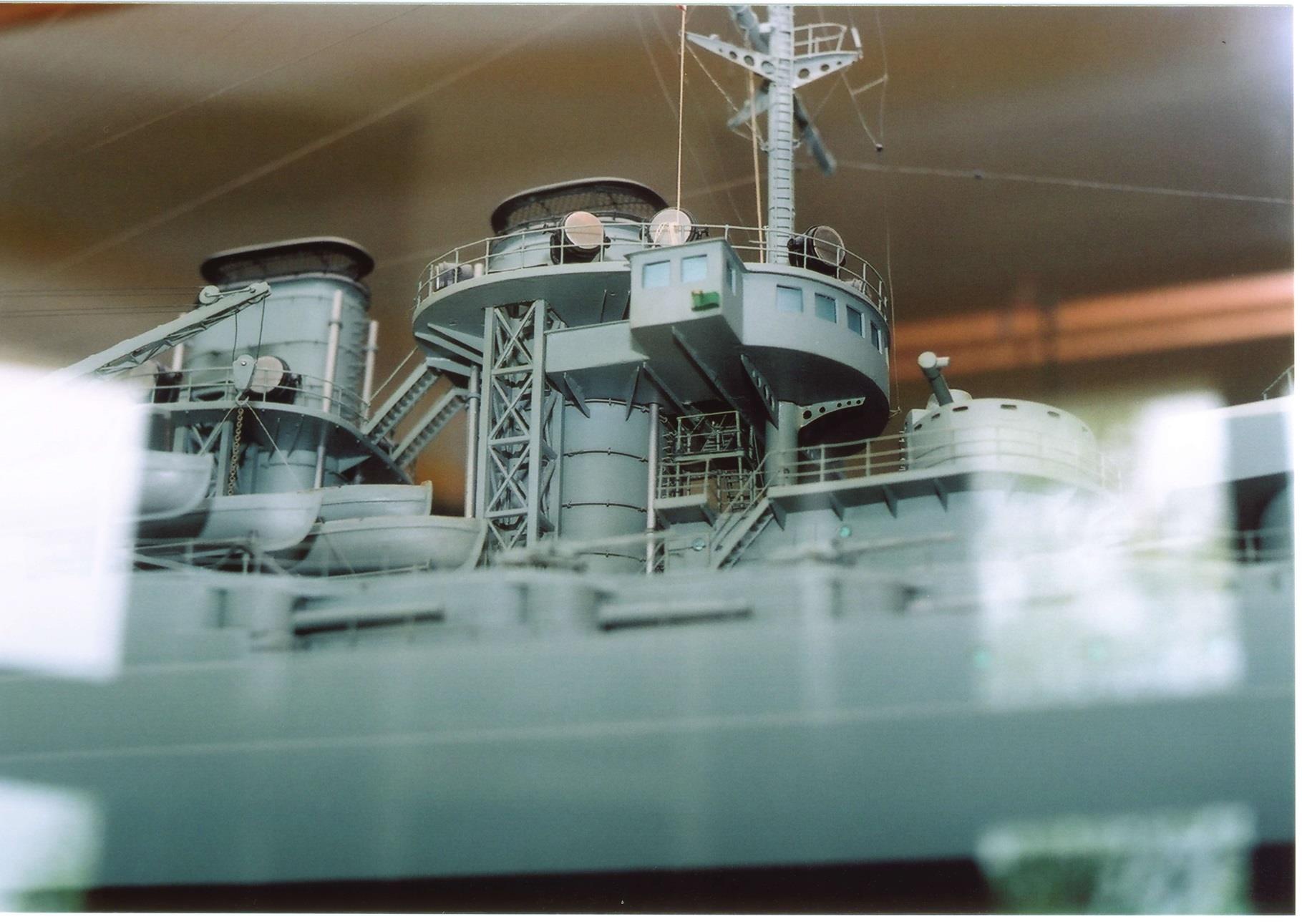
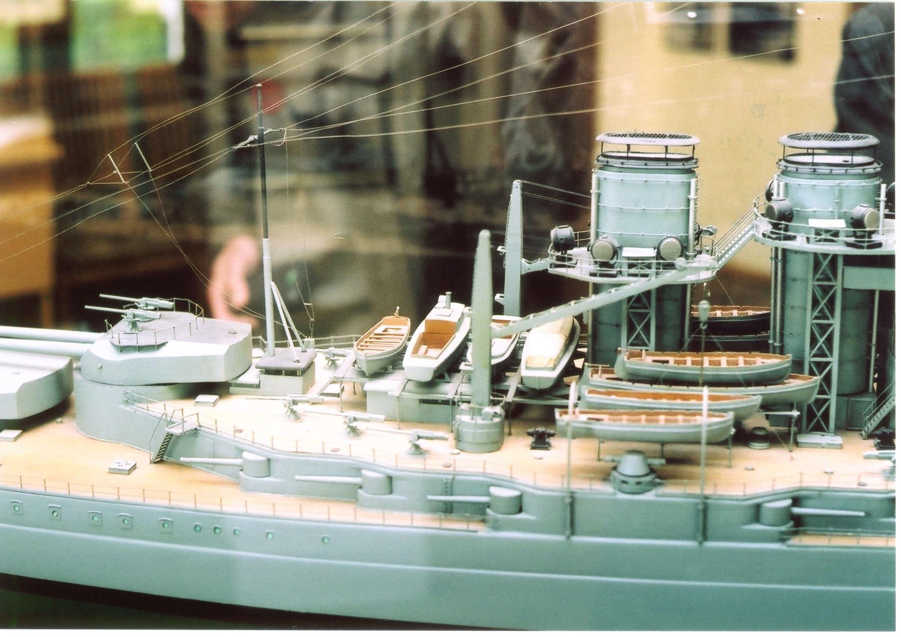
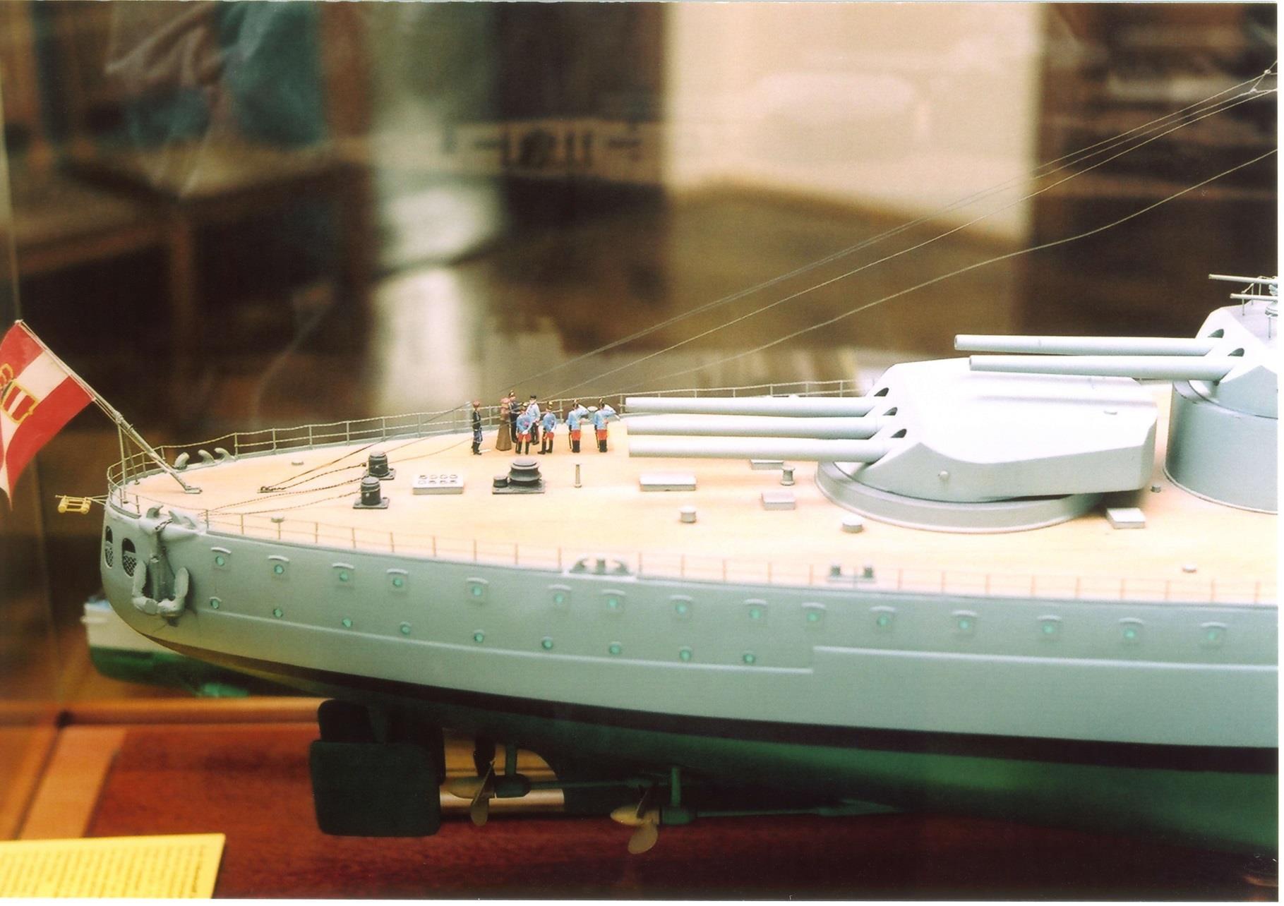
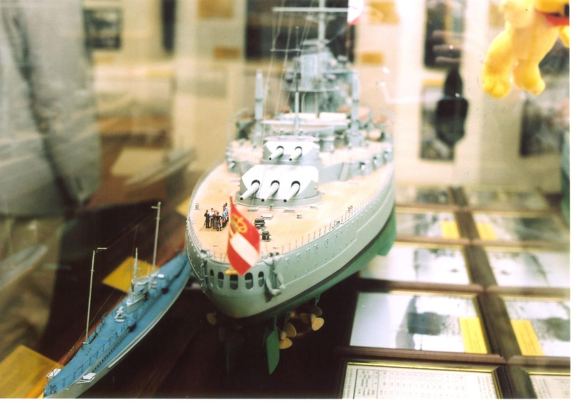
Austrian-Hungarian 24,500-ton battleship of the 'improved type TEGETTHOFF', which was not built in 1914 due to the outbreak of the war. 86 cm long model in the scale 1: 200 by Dipl.-Ing. Otto Schetina, Zeltweg. Digital photo for the book by L. Baumgartner / E.Sieche: The ships of the k.u.k. Kriegsmarine im Bild, Volume 2: 1896-1918; Publisher Stöhr, Vienna 2001.
  |
CAP RIBBONS: The military chancellery of the heir of the throne prepared in 1911 a list of possible names for future ships. As at least one ship would have to be constructed at the Hungarian yard “Ganz & Co. – Danubius” at least one or may be two ships would have a Hungarian name. The cap ribbons are of course pure fiction, the names taken from the 1911-list. Maybe that in 1914 other names would have been proposed. The last decision made the Emperor himself.
| |


| |
History


| |
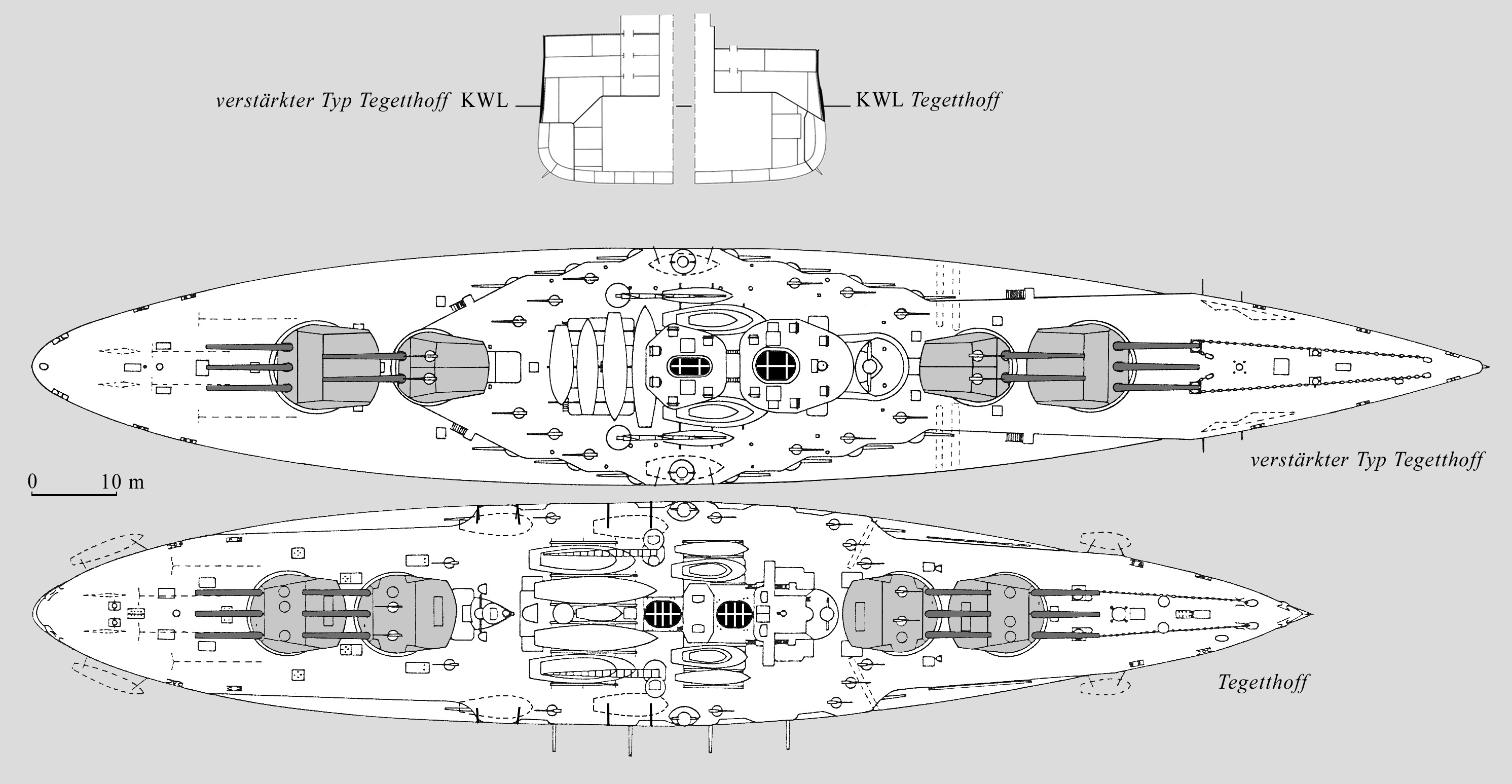
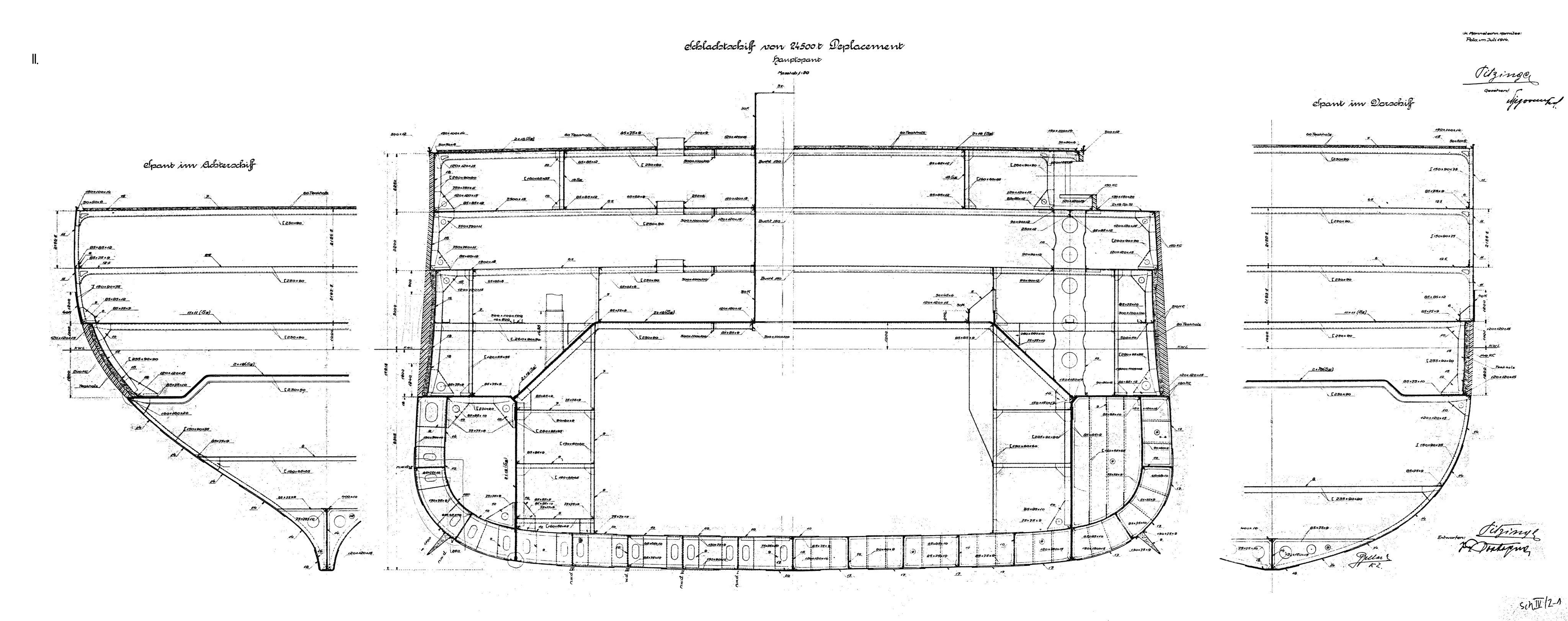
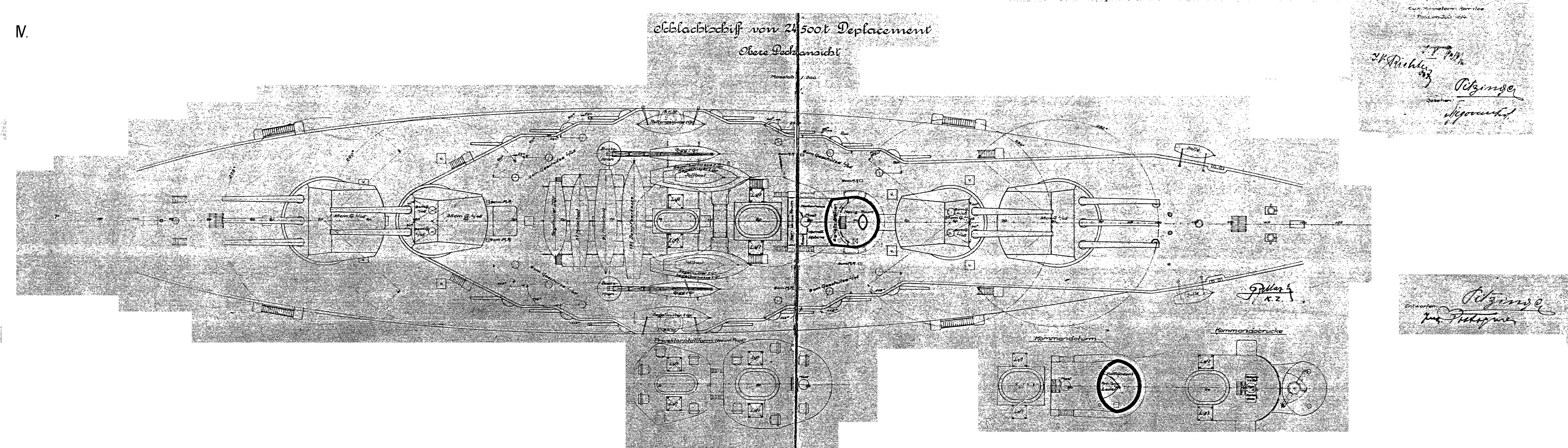
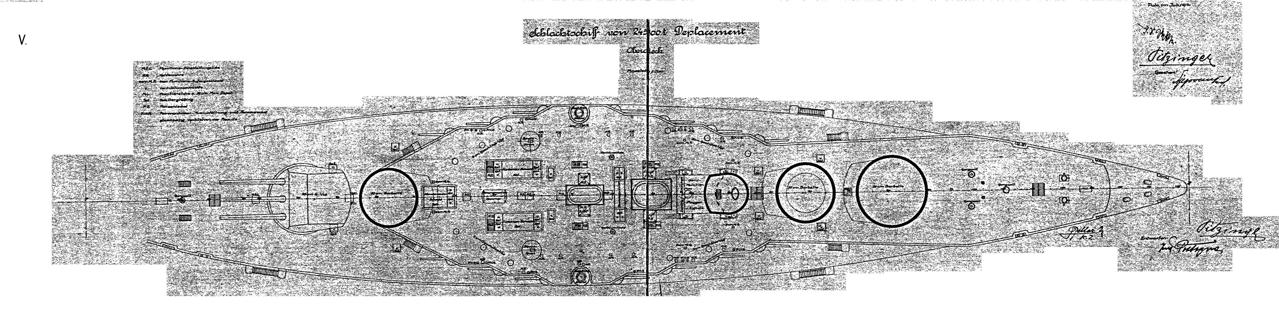
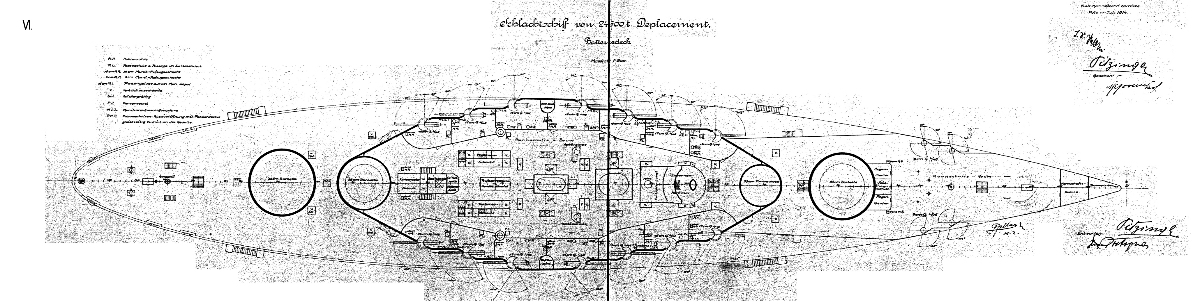
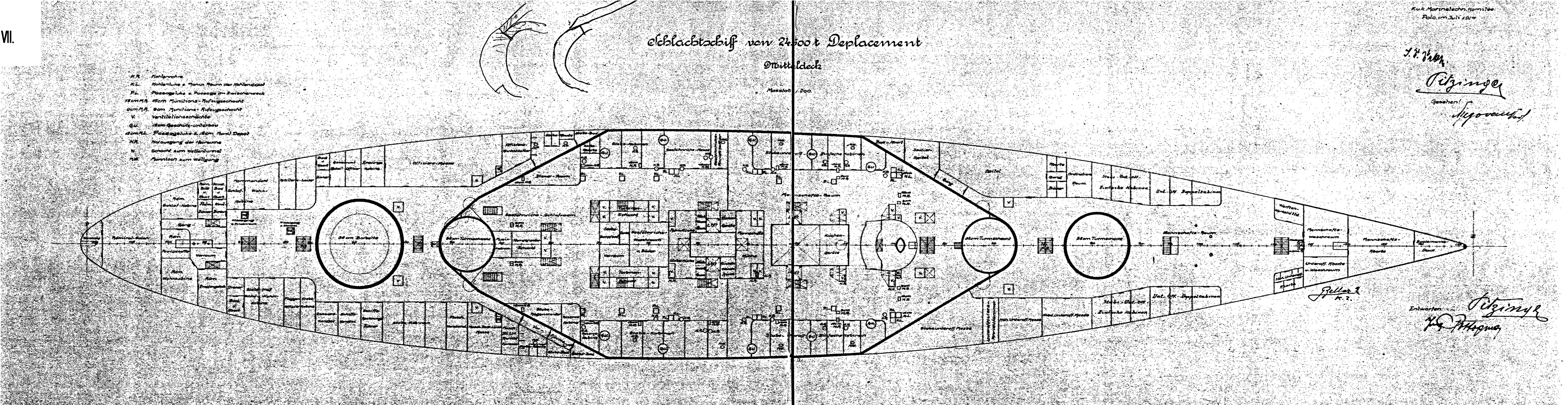
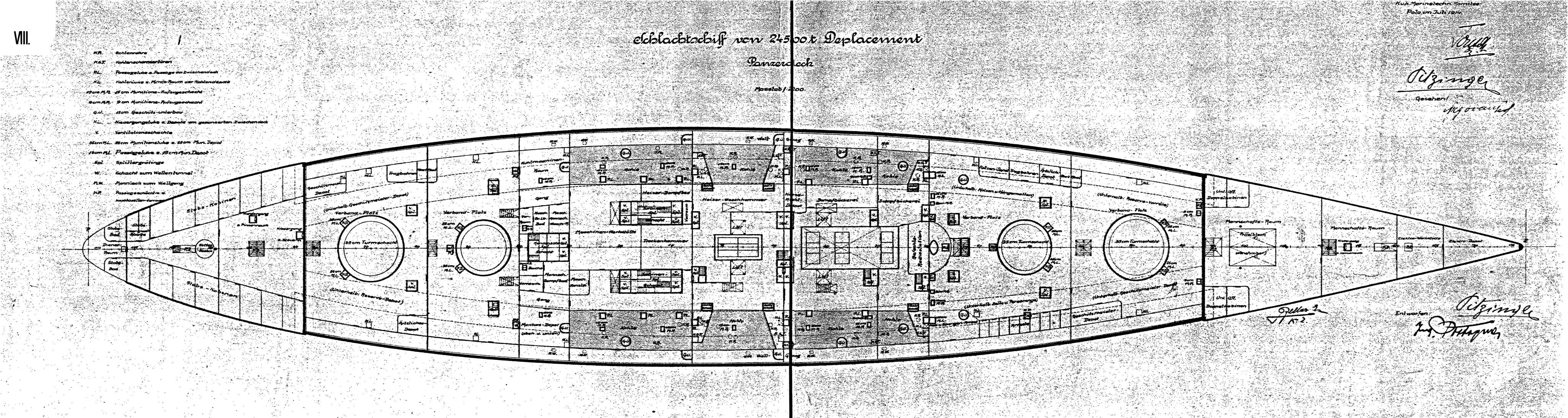
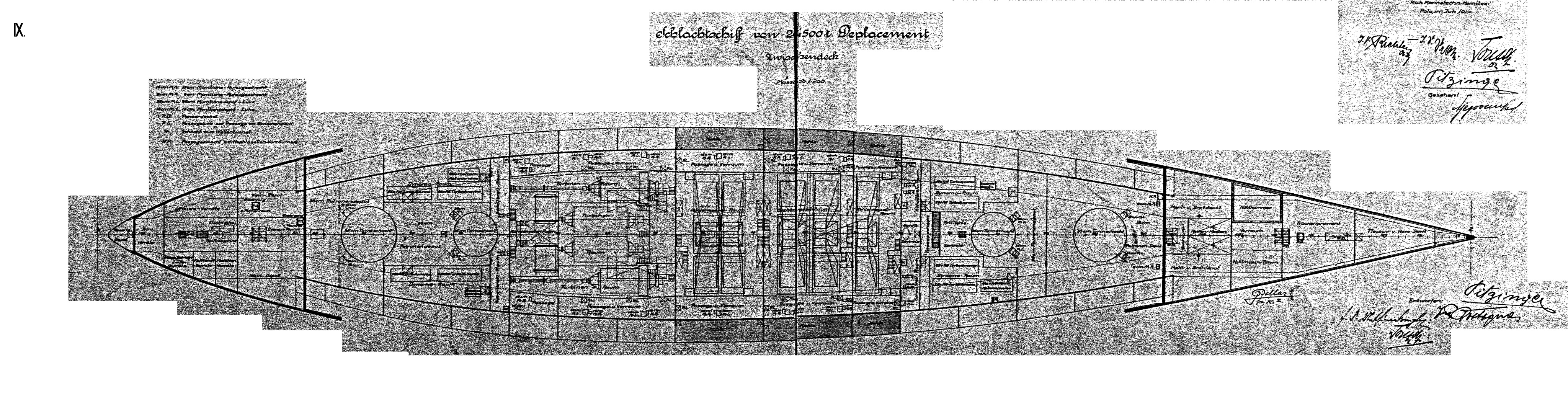
Improved Tegetthoff Class - Ship Plans
AutoCAD Ersatz Monarch Plans - by Andrew Wilkie


| |
Reference Documents - Improved Tegetthoff Class Battleship
File Name(s)
| The Two Battleship which were never built in Rijeka | Written by Mihály Krámli, PhD Budapest, Hungary |
| Improved Tegetthoff - Offer Letter | Construction offer letter to Skoda, STT and Witkswitzer (German) |
| Improved Tegetthoff - Protocol | Size assembly and armor of the to be built Battleships and Cruiser (German) |
| Improved Tegetthoff - Changes | 26 design changes to the battleship (German) |
| Improved Tegetthoff - Ship Specifications | Description of the ship's design, armament and dimensions (German) |
| |
| |
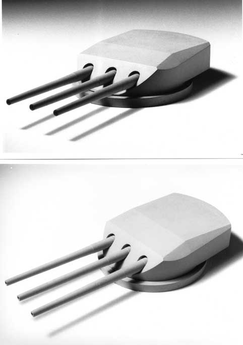
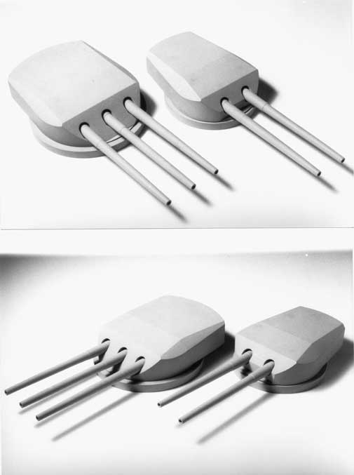
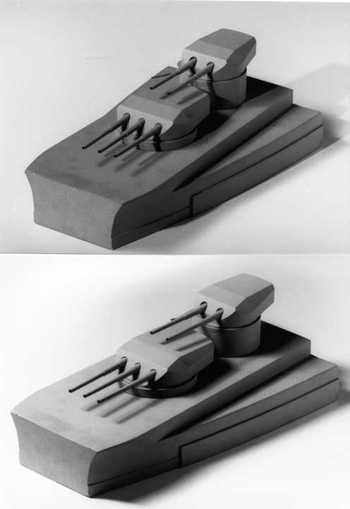
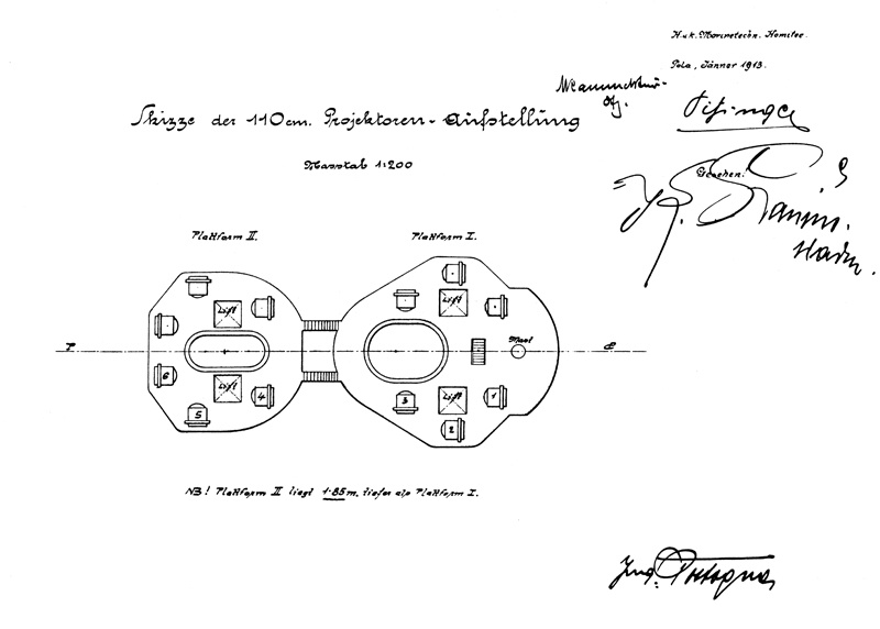
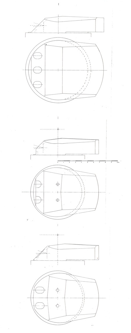
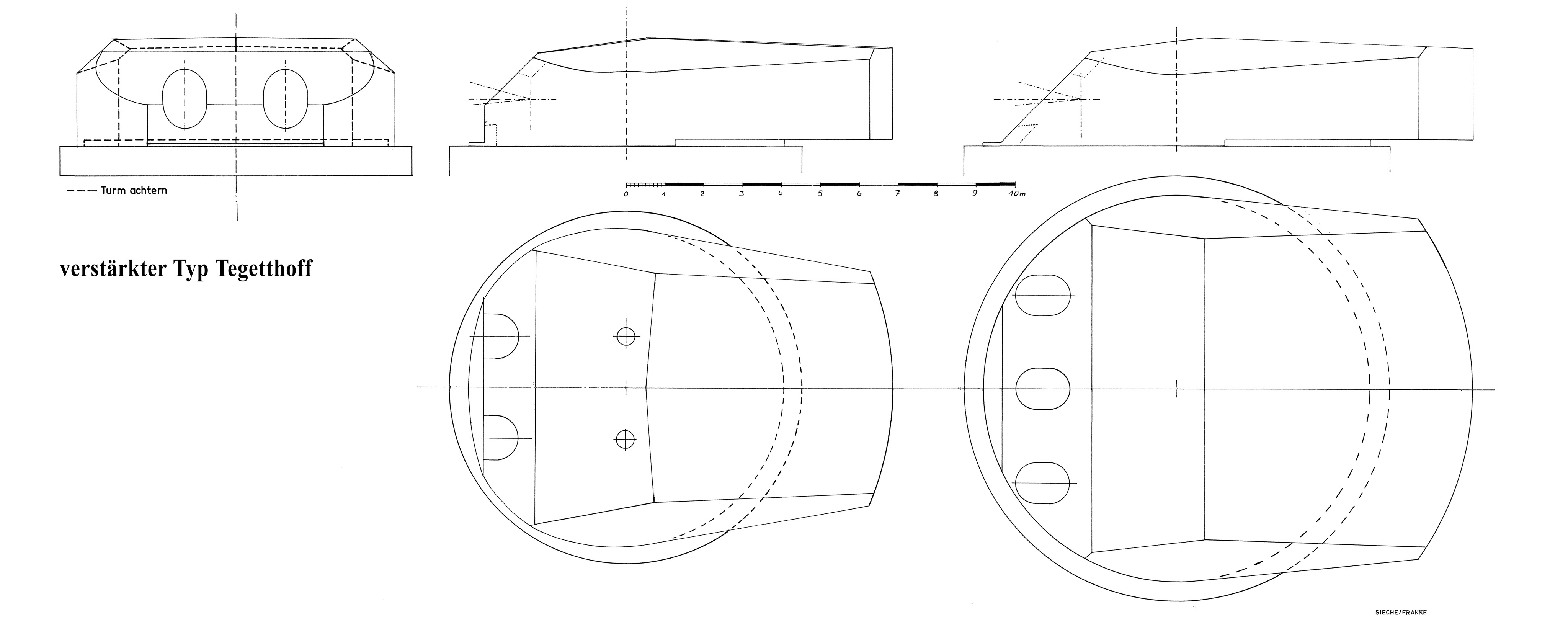
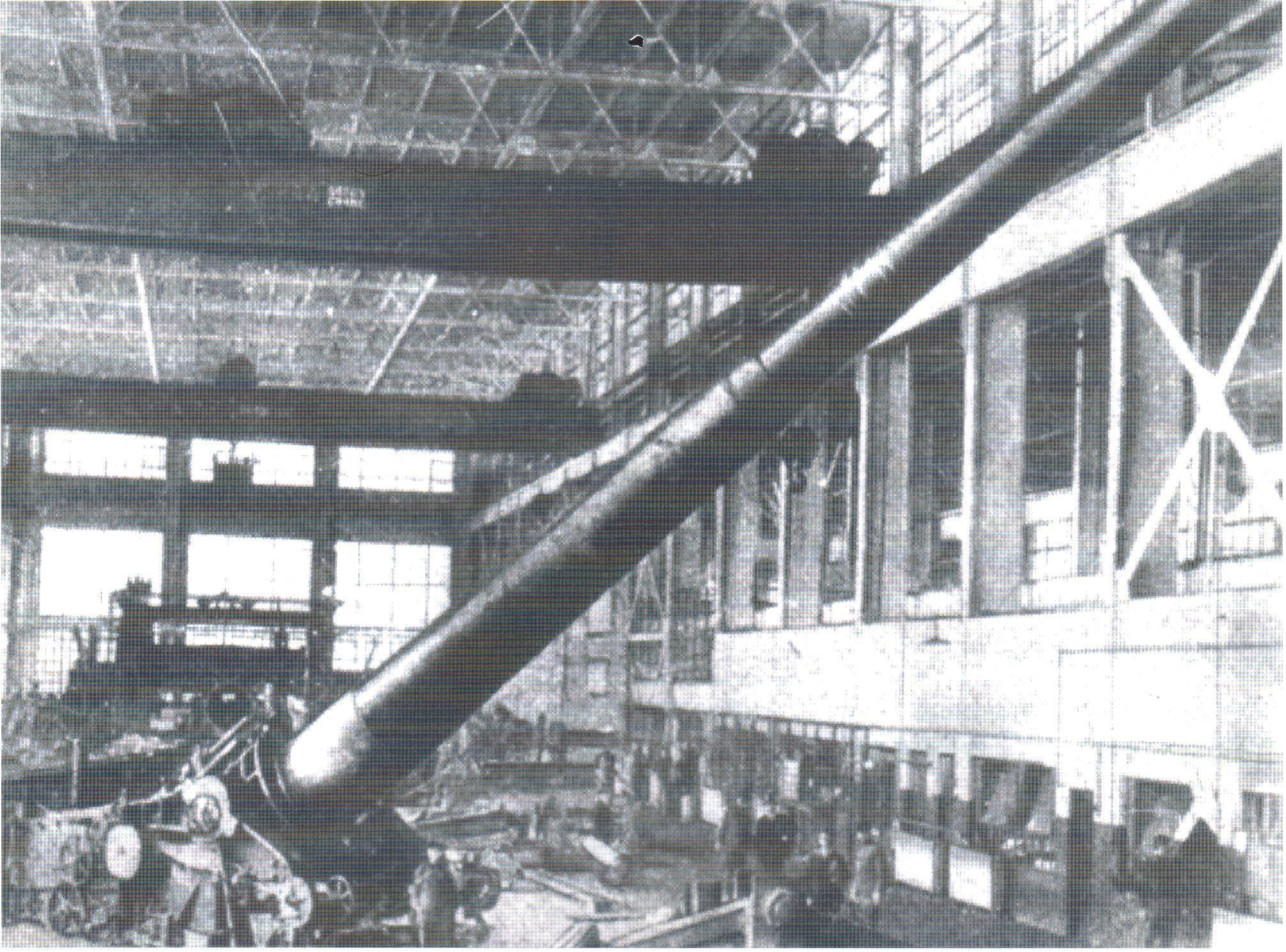
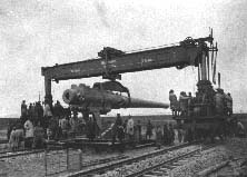
The 35cm guns of the Improved Tegetthoff class Battleships - by Erwin Sieche
| |
| |
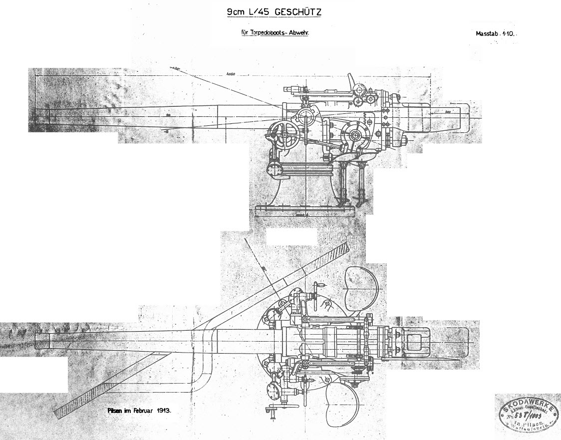
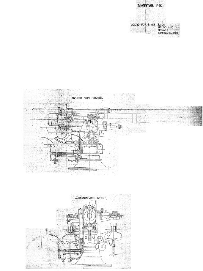
9 cm Anti-Torpedo Boat Gun - by Erwin Sieche
A new 9 cm gun was envisaged for the improved Tegetthoffs. (Hypothesis: as the foregoing 7 cm gun in fact had the calibre of 66 mm maybe that the 9 cm gun would have a calibre of 88 mm.) This gun did not exist, when the ship’s keel laying was scheduled. According to the war it was postponed and developed late in the war. These are scans of the original Skoda plans. In A-H nomenclature TAG means ‘Torpedoboot Abwehr Geschuetz”, e. g. Anti torpedoboot gun. In consequence BAG means “Ballon Abwehr Geschuetz”, a somehow antiquated name, it was simply a AA gun. L/45 means the length of the barrel, in English described as cal 45.


| |
Official files and plans
Oesterreichisches Staatsarchiv/Kriegsarchiv, Vienna
Files II GG 1911 4D/4 2/7, 2/21, 7/9; I GG 1913 I-4/11; II GG 1914 47 C 6/4-9/5, II GG 1914 IV B 1/7
Collection of ship’s plans
Sch IV/1-2 to Sch IV/1-6
Reference books
Gray Randal (Editor), Conway's all the World's Fighting Ships 1906-1921, London 1985, page 335
Prasil, Michal, Skoda Heavy Guns, Atglen, PA/USA, 1997
Schirmer, Hermann, Das Geraet der schweren Artillerie vor, in und nach dem Weltkrieg, Berlin 1937, page 374
Periodicals
Die Flagge, Vienna, August 1913, pages 294, 295
HADITECHNIKA, Budapest, 3/1972, page 54
MARINE - Gestern, Heute, Vienna, 4/1977, page 118
Marine Rundschau, Germany, October 1938, page 752f
Warship International, Toledo USA, 2/1971, page 186, 1/1972, page 85, 4/1972, page 443, 2/1974, page 173ff, 3/1980, page 281, 1/1984, page 120f, 3/1985 page 320f
| |
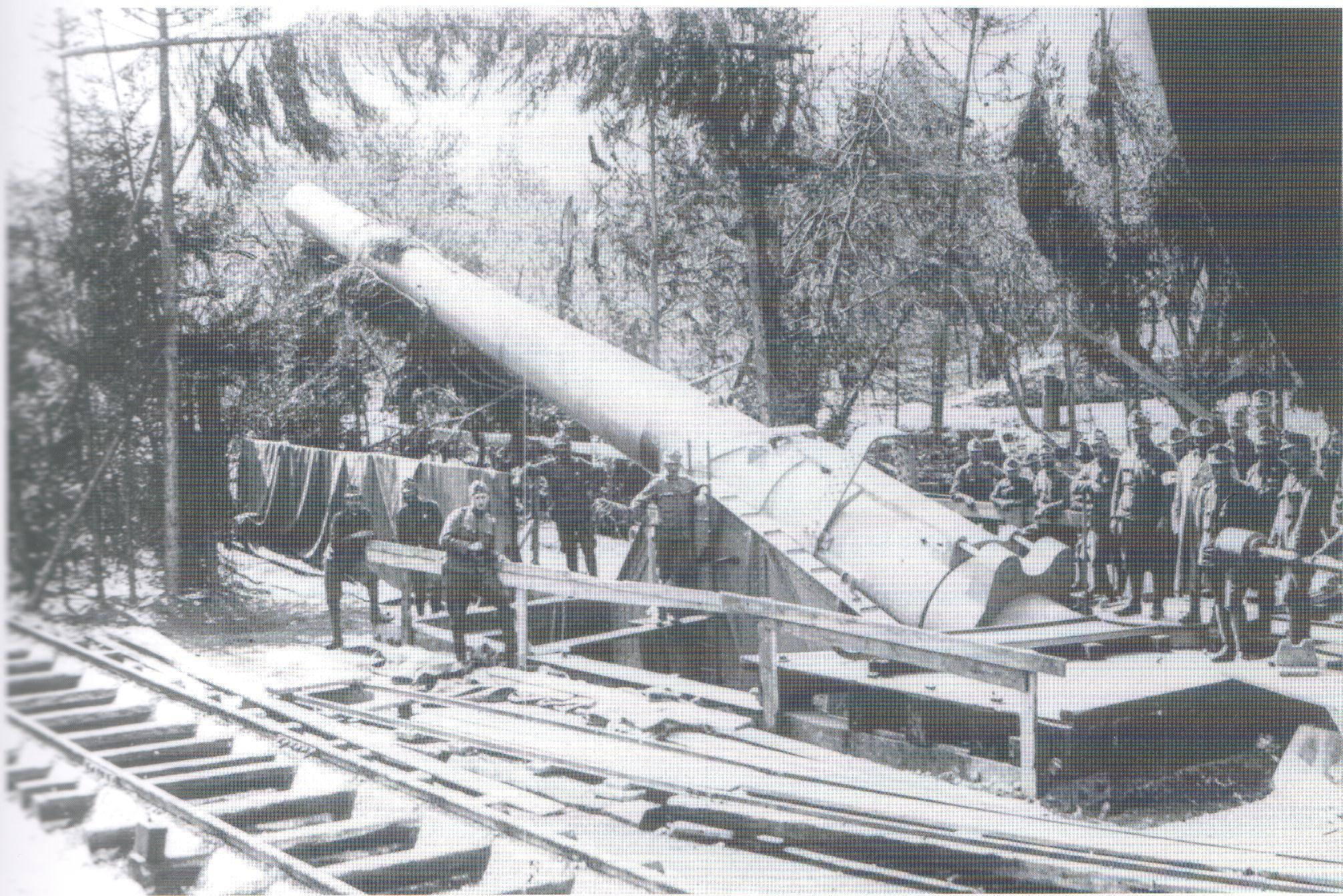
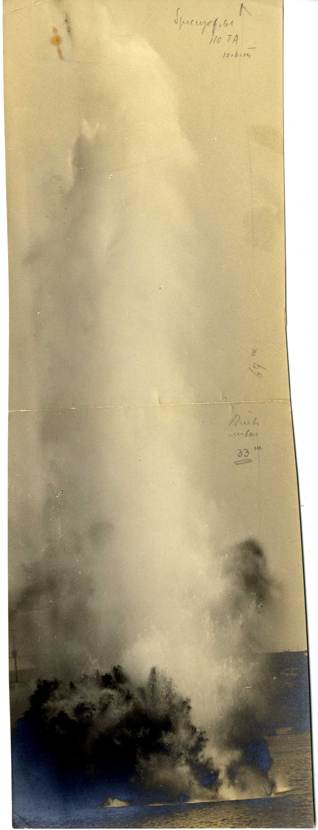
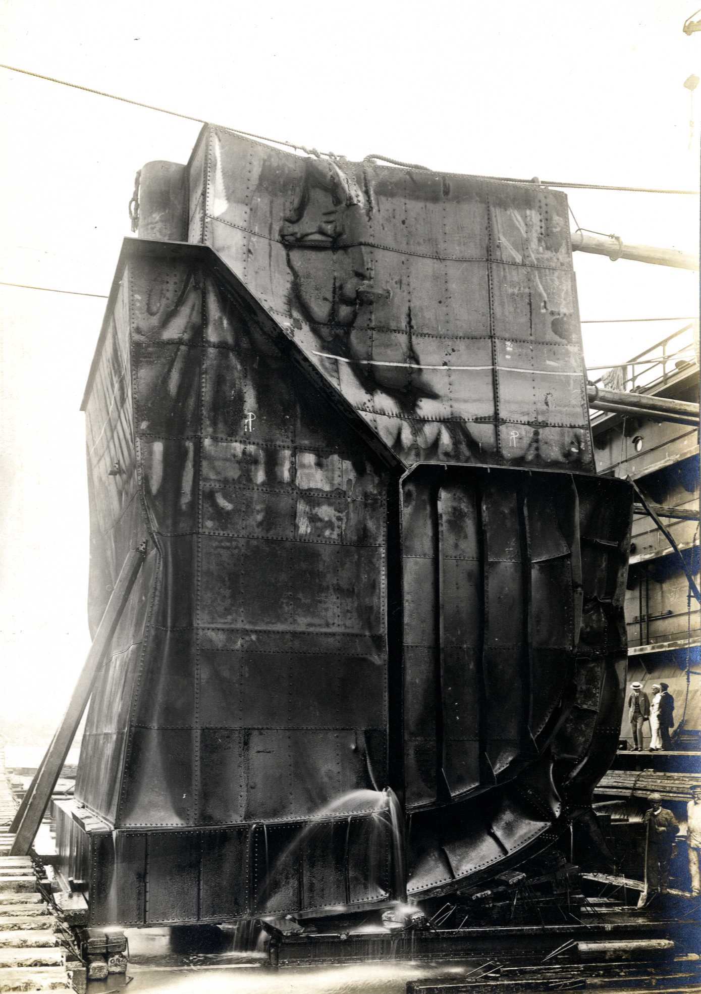
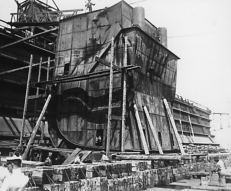
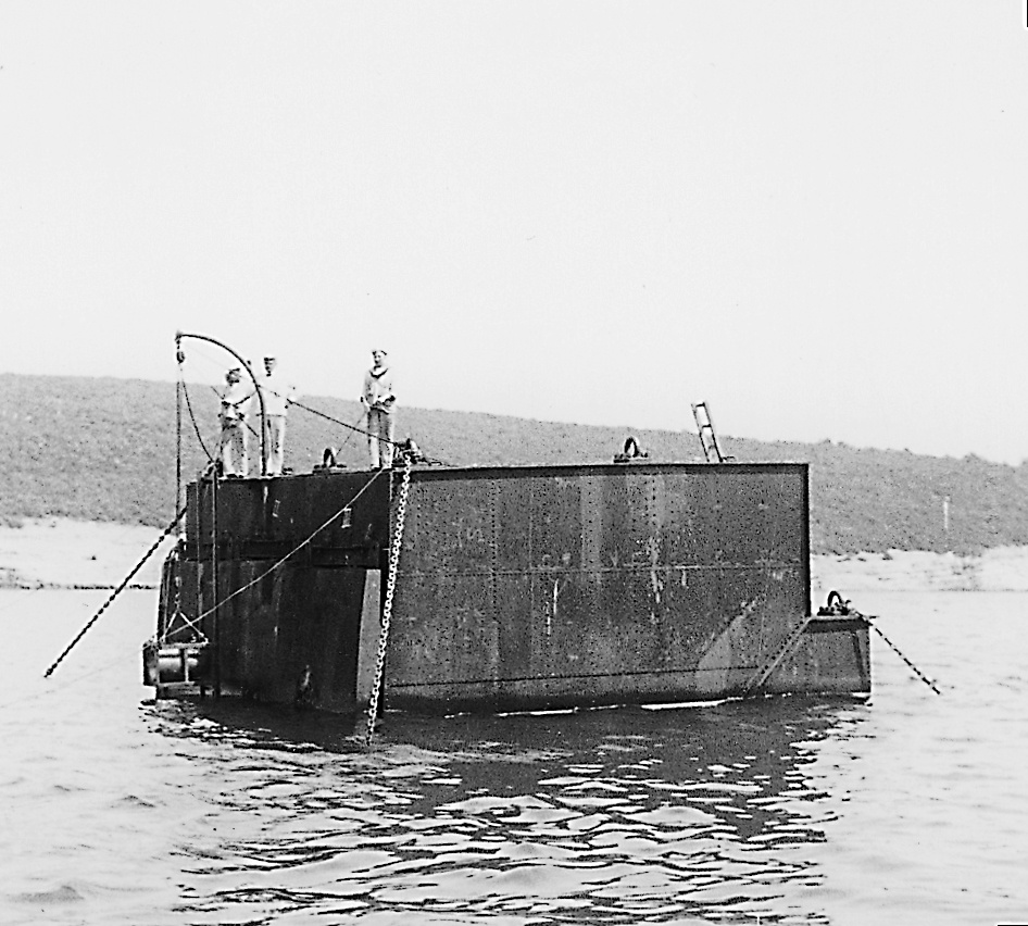
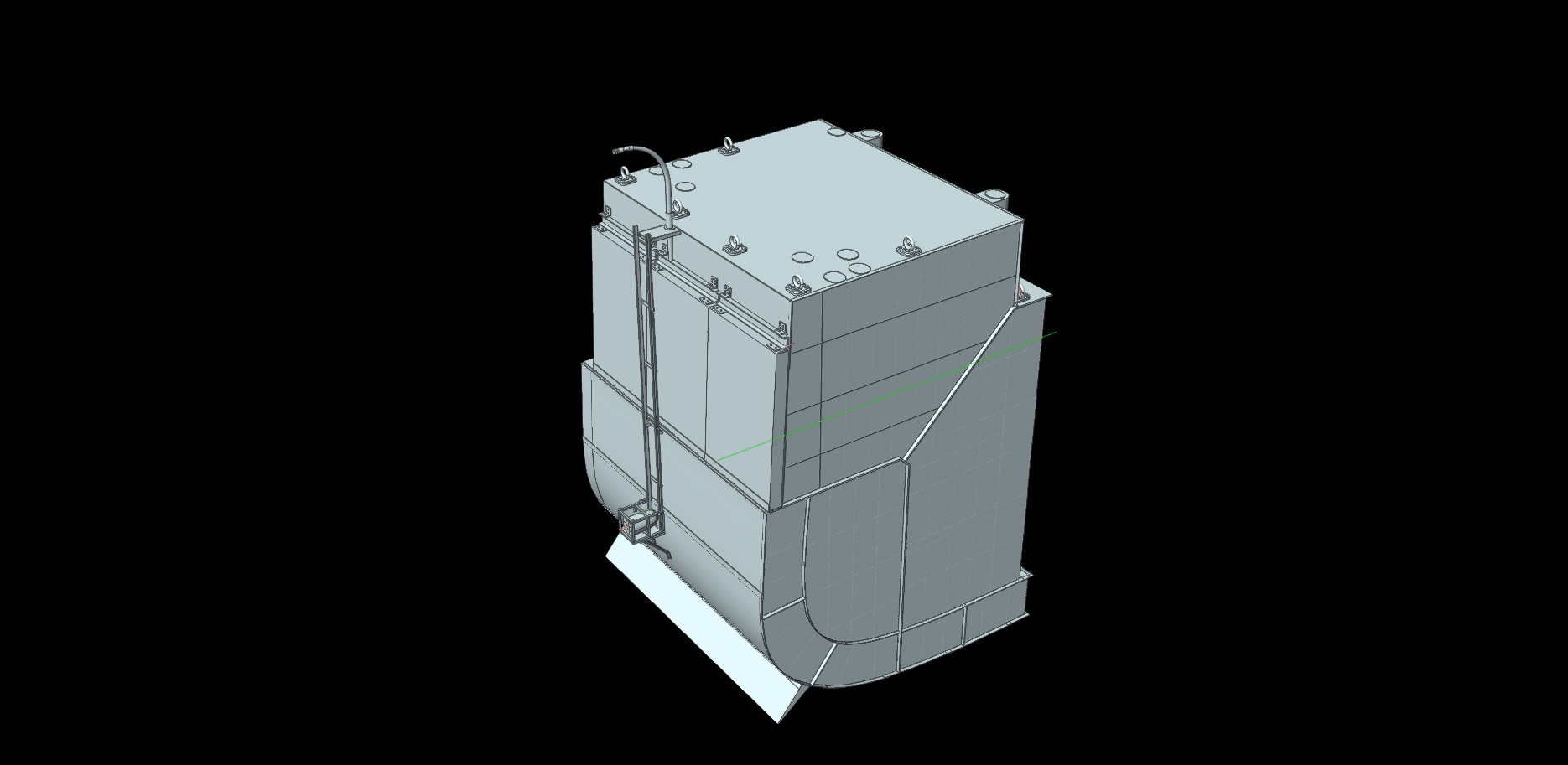
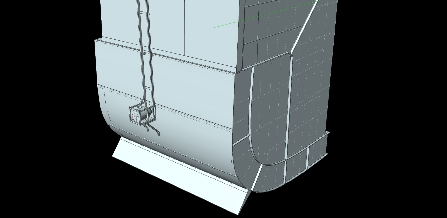
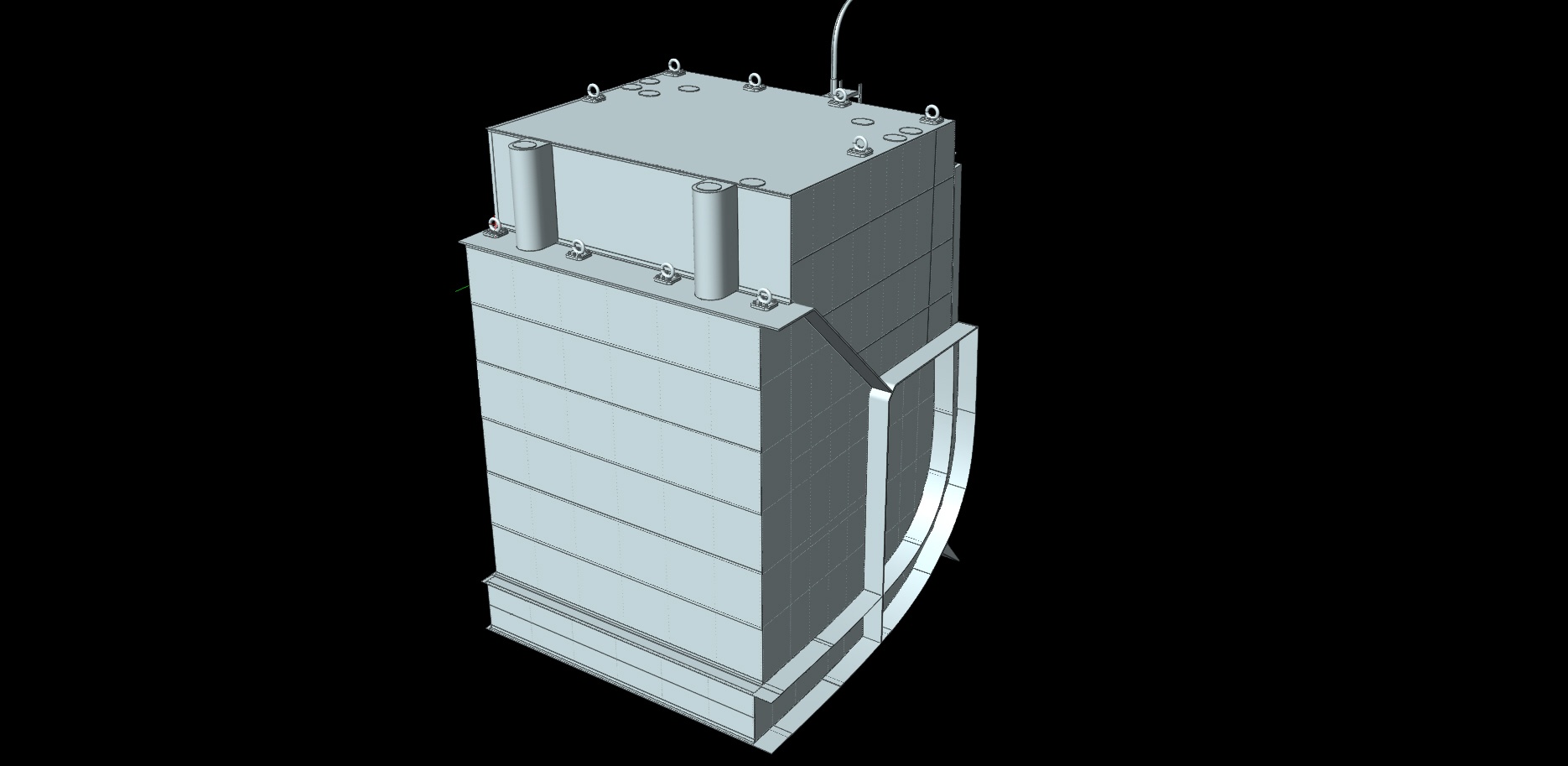
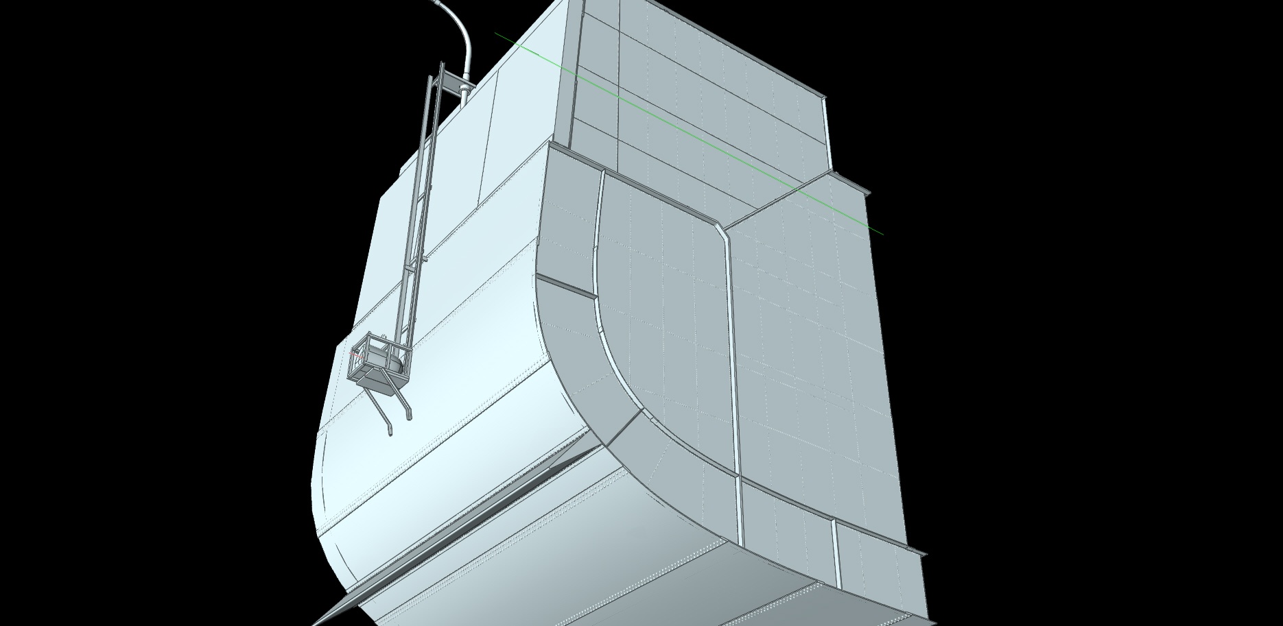
TEST BED - Explosive Object
Type of ship: Test object, a fuselage section of the ship to be tested
To optimize the underwater protection scheme of the abortive super-dreadnoughts of the ‘improved TEGETTHOFF-type’, dubbed ‘Ersatz MONARCH-class’ of 1914/15 a special TEST BED was built and underwent blast tests in March 1914. The complete technical documentation of these tests –filed as II GG 4 K-1 in 1914– was probably sacked immediately after the war by one of the Allied fact-finding missions as ‘prize of outstanding technical importance’ and are missing today in the files of the Austrian State Archive/War Archive. Only a handful of photographs survived, as shown here.
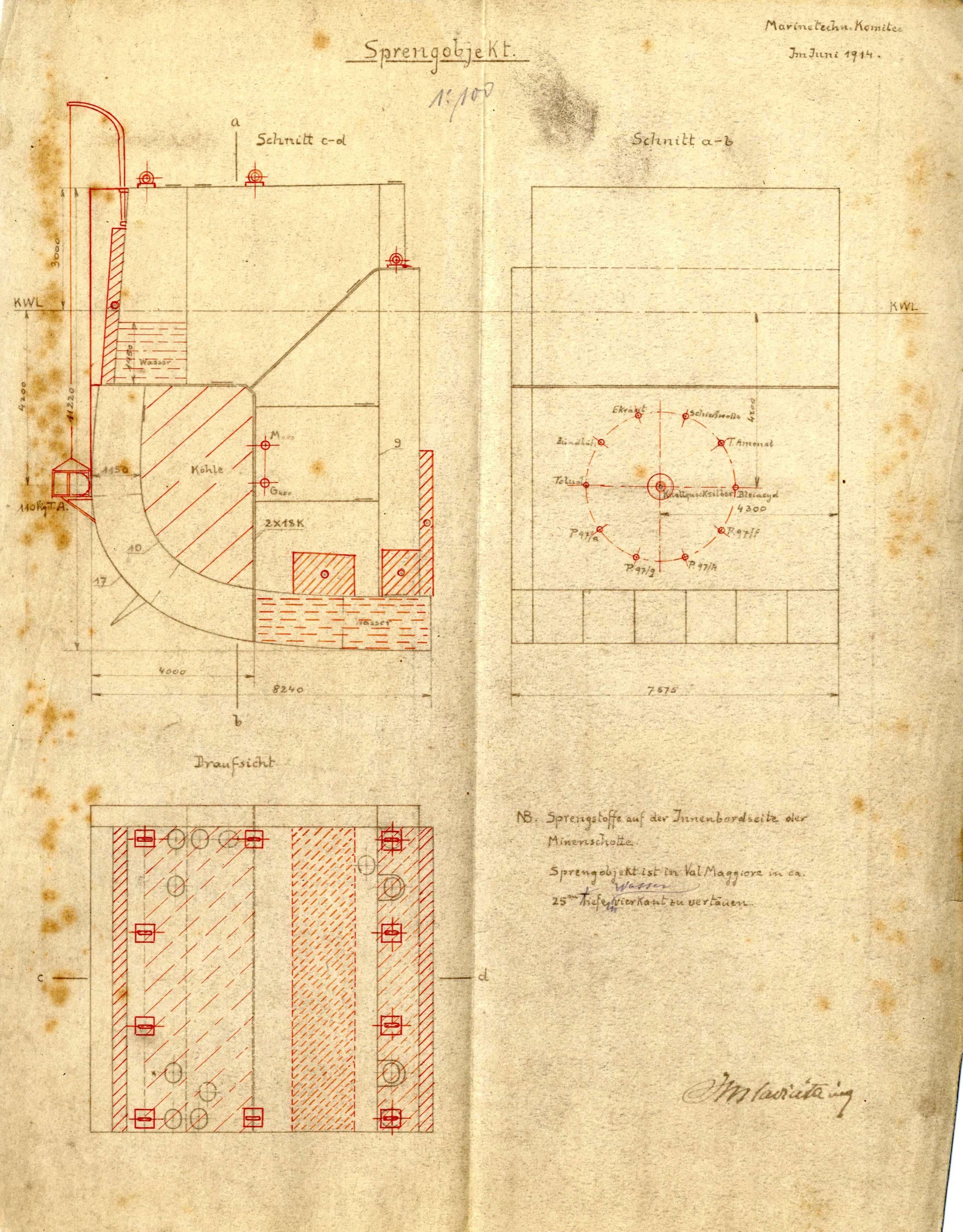
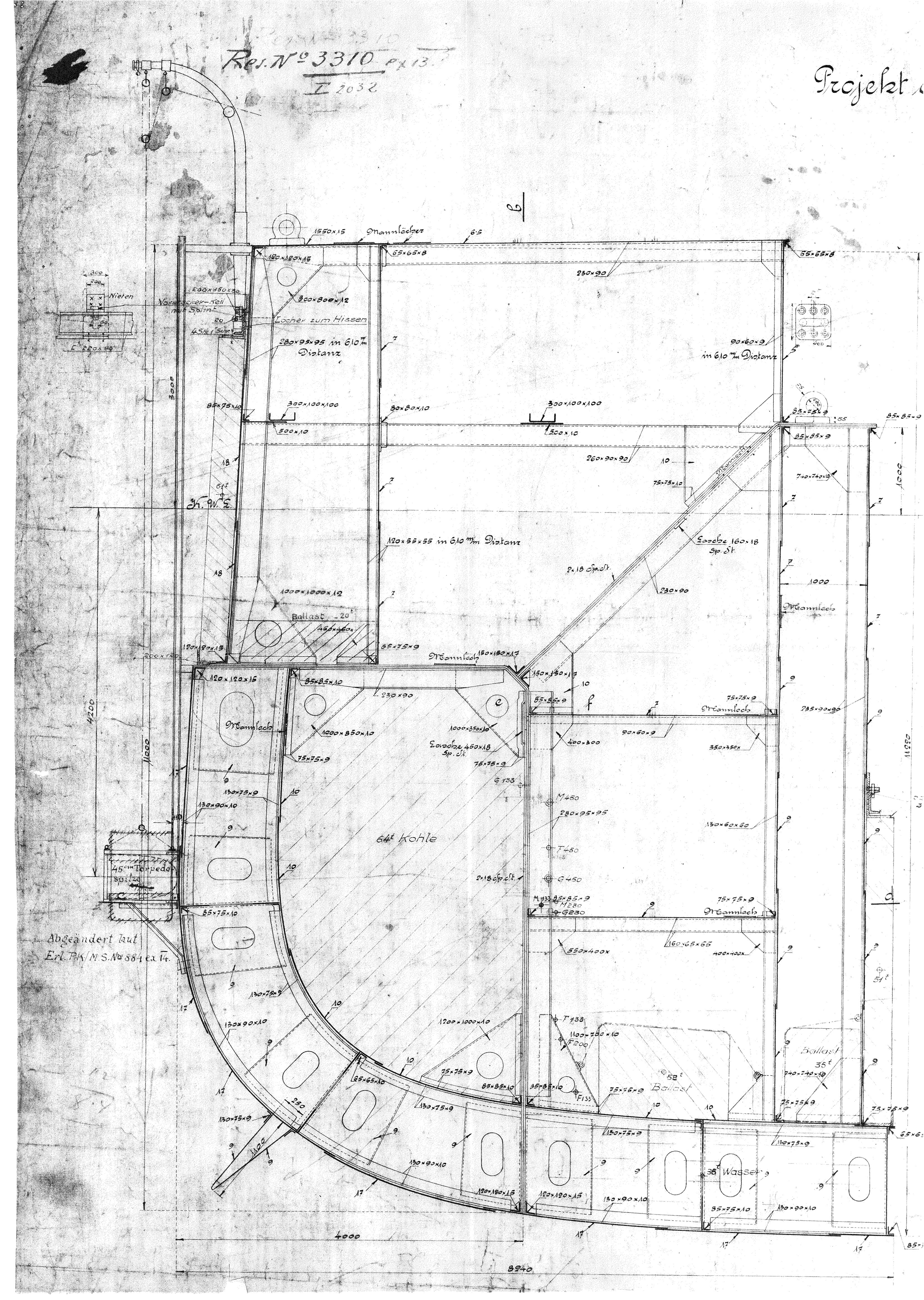
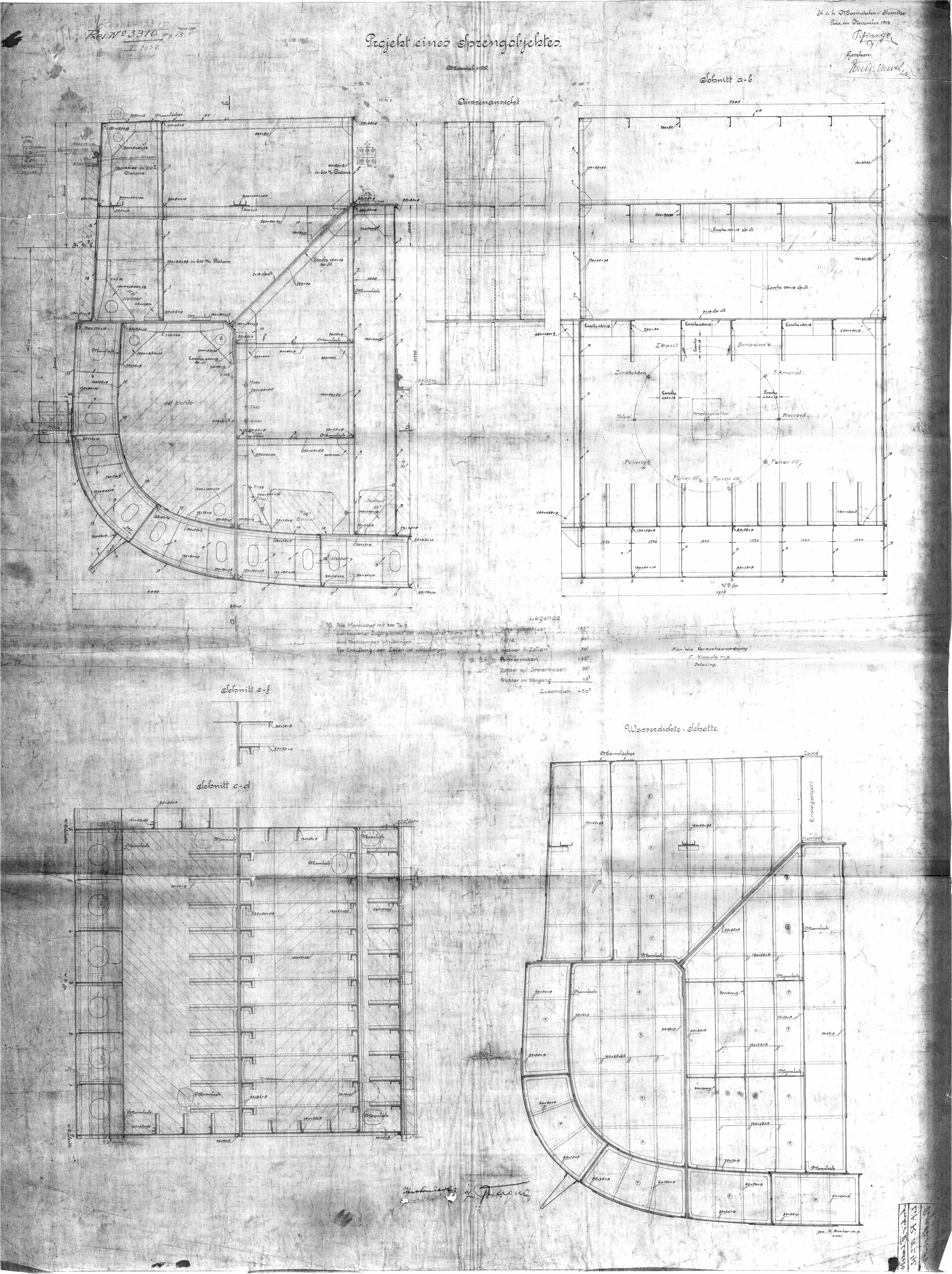
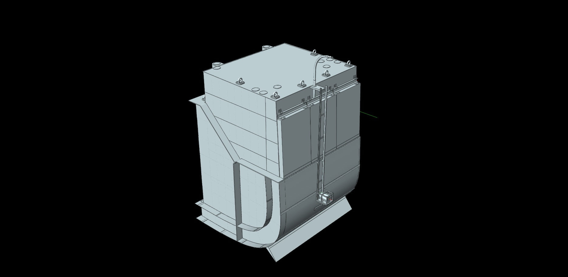
AutoCAD & JPG Drawings
| Test Bed Plans-AutoCAD.pdf | Drawn by Andrew W. Wilkie |
| Test Bed Plans - Complete-reduced.jpg | High Resolution Bitmap of Test Bed Plans |
| |
List of all different MTK-Projects of the 'improved TEGETTHOFF'-type
| Date | Displacement & Dimensions | Armament |
| Design I: December 1911 | 22.000 t | only triple turrets |
| 161 x 27,6 x 8,4 m | 12 x 30,5 cm cal 45 | |
| 22 x 15 cm cal 50 | ||
| 24 x 7,5 cm cal 50 | ||
| 4 twin-casemates fore | ||
| 2 twin-casemates aft | ||
| Design II: December 1911 | 23.400 t | twins superimposed over triple turrets |
| 165 x 27,8 x 8,4 m | 10 x 34,5 cm cal 45 | |
| 22 x 15 cm cal 50 | ||
| 24 x 7,5 cm cal 45 | ||
| 4 twin-casemates fore | ||
| 2 twin-casemates aft | ||
| Design III: December 1911 | 24.500 t | twins superimposed over triple turrets |
| 165 x 27,8 x 84 m | 10 x 34,5 cm cal (?) | |
| 22 x 15 cm cal 50 | ||
| 24 x 7,5 cm cal (?) | ||
| 4 twin-casemates fore | ||
| 2 twin-casemates aft | ||
| Design IV: December 1911 | 23.400 t | twins superimposed over triple turrets |
| 165 x 27,8 x 8,4 m | 10 x 34,5 cm cal 45 | |
| 22 x 15 cm cal 50 | ||
| 24 x 7,5 cm cal 45 | ||
| Design V: February 1912 | 22.000 t | only triple turrets |
| 161 x 27,6 x 8,4 m | 12 x 30,5 cm cal 45 | |
| 22 x 15 cm cal 50 | ||
| 24 x 7,5 cm cal 50 | ||
| 4 twin-casemates fore | ||
| 2 twin-casemates aft | ||
| partially reduced poop deck | ||
| Design VI: May 1912 | 25.200 t | 1 triple, 4 twin turrets |
| 175 x 28,5 x 8,5 m | 11 x 34,5 cm cal 45 | |
| 16 x 15 cm cal 50 | ||
| 18 x 7,5 cm cal 50 | ||
| one double story casemate fore | ||
| focsle extending until fore funnel | ||
| Design VII: May 1912 | 25.200 t | only triple turrets |
| 175 x 28,5 x 8,5 m | 12 x 34,5 cm cal 45 | |
| 16 x 15 cm cal 50 | ||
| 18 x 7,5 cm cal 50 | ||
| one double story casemate fore | ||
| focsle extending until fore funnel | ||
| Design VIII: May 1912 | 25.200 t | 3 triple, 2 twin turrets |
| 175 x 28,5 x 8,5 m | 13 x 34,5 cm cal 45 | |
| 16 x 15 cm cal 50 | ||
| 18 x 7,5 cm cal 50 | ||
| one double story casemate fore | ||
| focsle extending until fore funnel | ||
| Design IX: May 1912 | 25.200 t | 2 triple, 3 twin turrets |
| 175 x 28,5 x 8,5 m | 12 x 34,5 cm cal 45 | |
| 14 x 15 cm cal 50 | ||
| 18 x 7,5 cm cal 50 | ||
| one double story casemate fore | ||
| focsle extending until fore funnel | ||
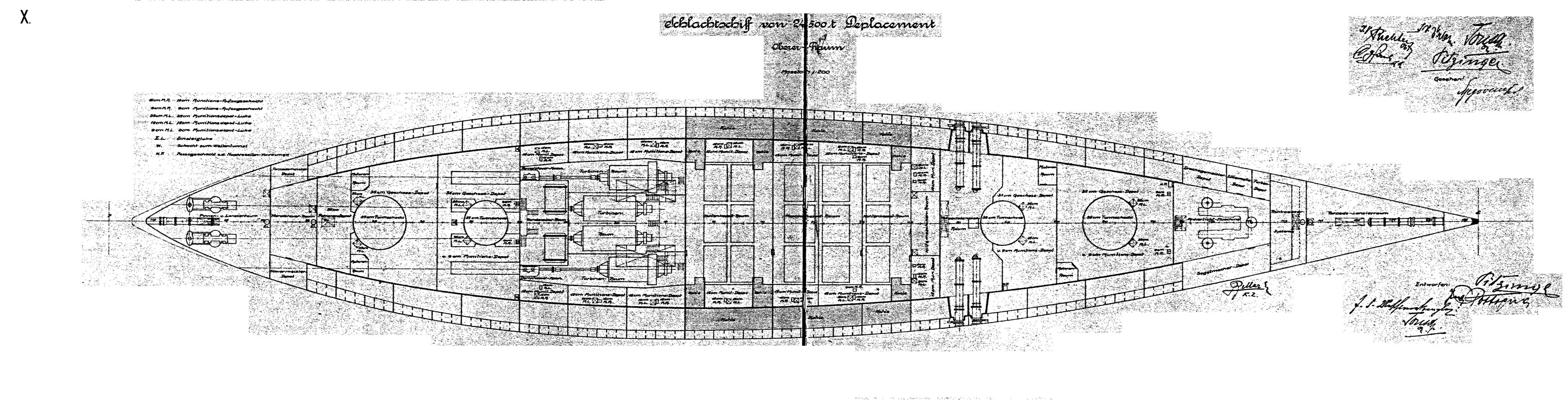
| Design X: January 1913 | 24.500 t | triple superimposed over twin turrets |
| 10 x 35 cm cal 45 | ||
| 18 x 15 cm cal 50 | ||
| 22 x 9 cm cal 45, including 6 AA guns | ||
| double story casemates fore | ||
| Design XI: April 1913 | 24.500 t | twins superimposed over triple turrets |
| 172 x 28,5 x 8,4 m | 10 x 35 cm cal 45 | |
| 18 x 15 cm cal 50 | ||
| 20 x 9 cm cal 45, including 4 AA guns | ||
| double story casemates fore | ||
| Design XII: January 1914 - Pre-project | 29.600 t | only 4 triple turrets |
| 194 x 29 x 8,5 m | 12 x 35 cm cal 45 | |
| 18 x 15 cm cal 50 | ||
| 18 x 9 cm cal 45, including 10 AA guns | ||
| double story casemates fore | ||
| Design XIII: January 1914 - Pre-project | 32.000 t | twins superimposed over triples, 3 triples, 2 twins |
| 196,5 x 29,5 x 8,4 m | 13 x 35 cm cal 45 | |
| 18 x 15 cm cal 50 | ||
| 18 x 9 cm cal 45, including 10 AA guns | ||
| double story casemates fore | ||
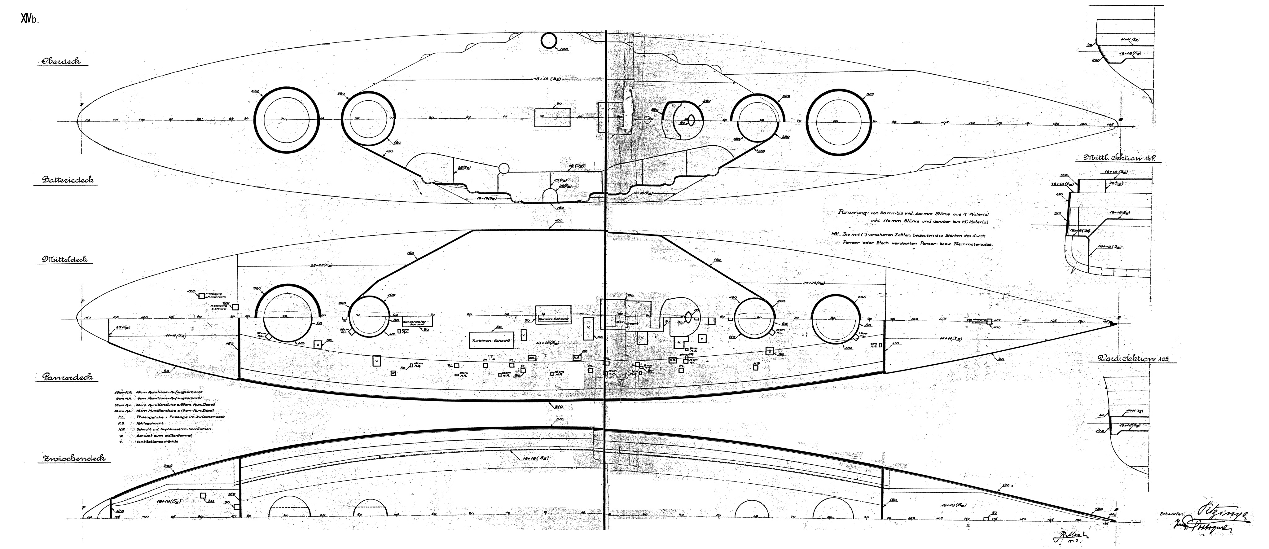
| Design XIV: January 1914 | 24.500 t | triple superimposed over twin turrets |
| 172 x 28,5 x 8,4 m | 10 x 35 cm cal 45 | |
| 14 x 15 cm cal 50 | ||
| 22 x 9 cm cal 45, including 12 AA guns | ||
| double story casemates fore | ||
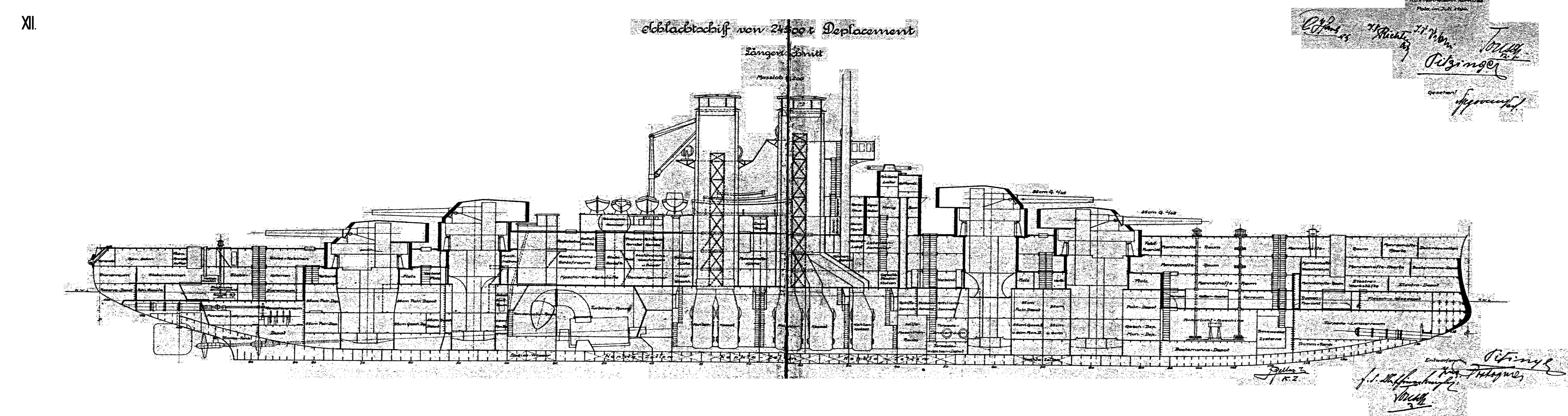
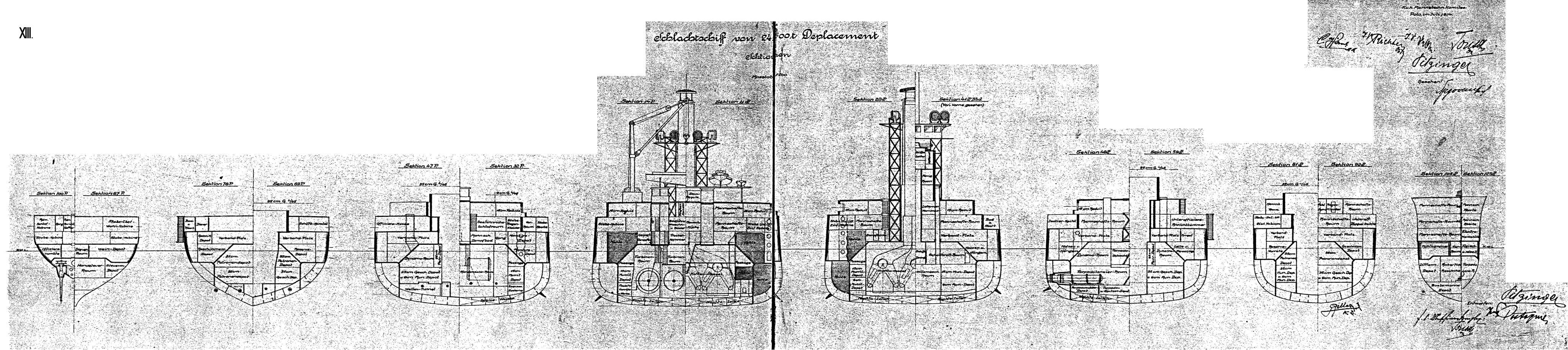
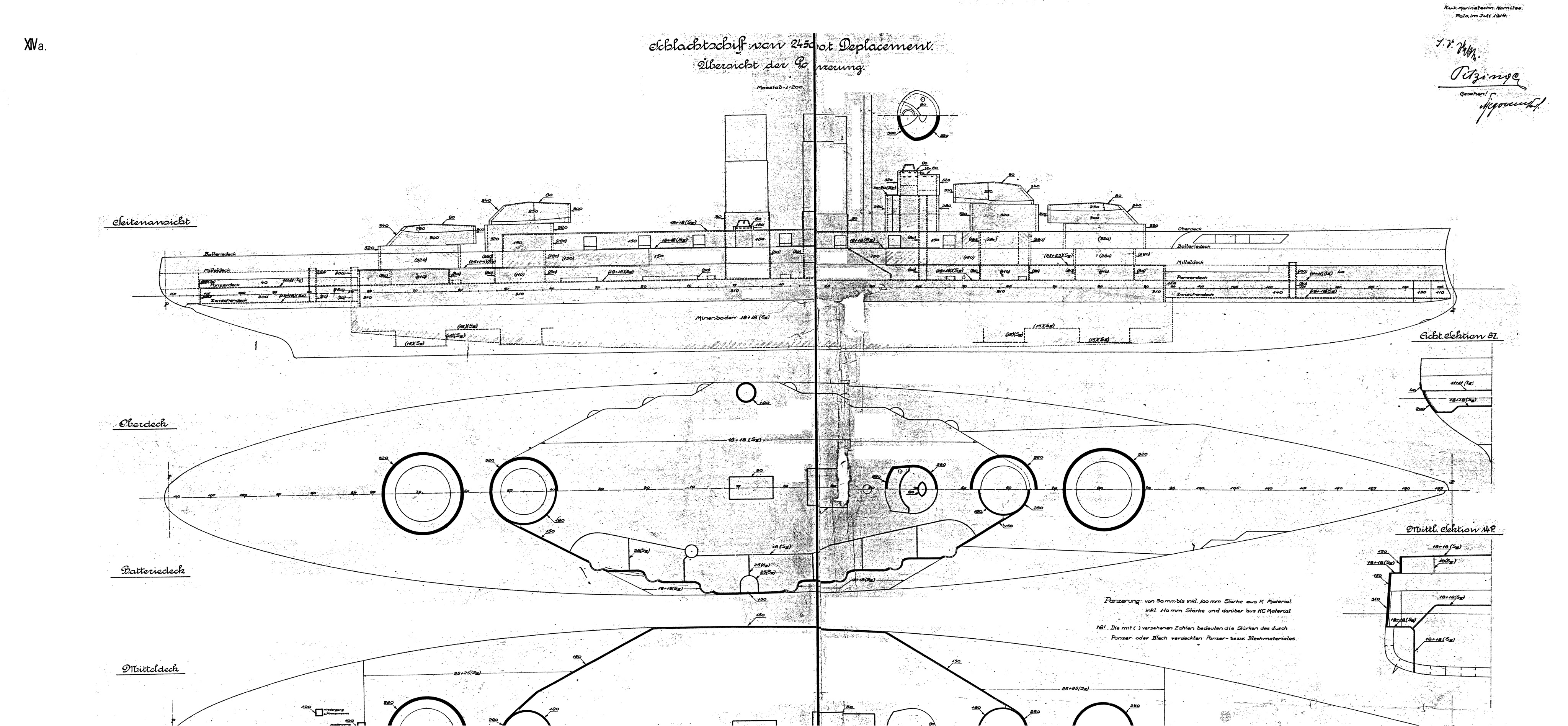
| Design XV: July 1914 | 24.500 t | twins superimposed over triple turrets |
| 172 x 28,5 x 8,4 m | 10 x 35 cm cal 45 | |
| 14 x 15 cm cal 50 | ||
| 20 x 9 cm cal 45, including 12 AA guns | ||
| |
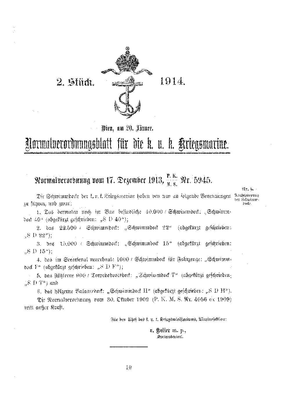
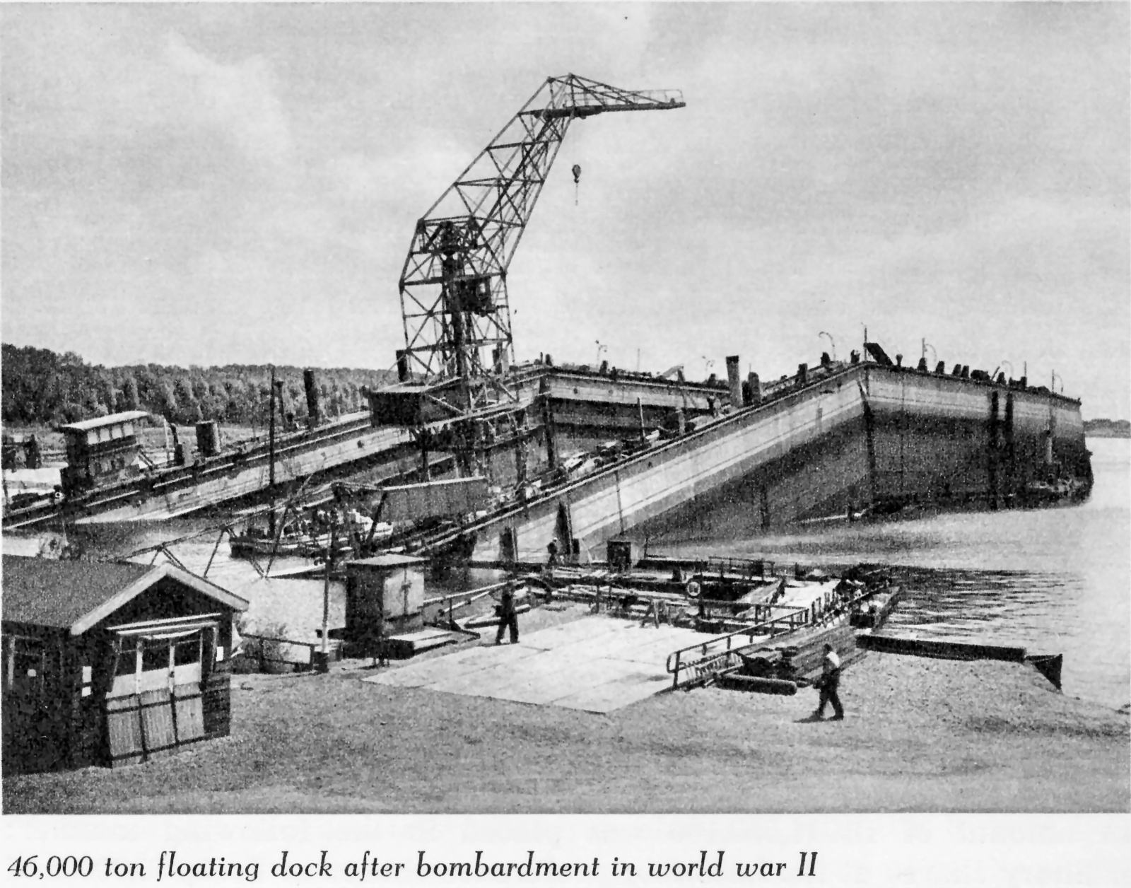
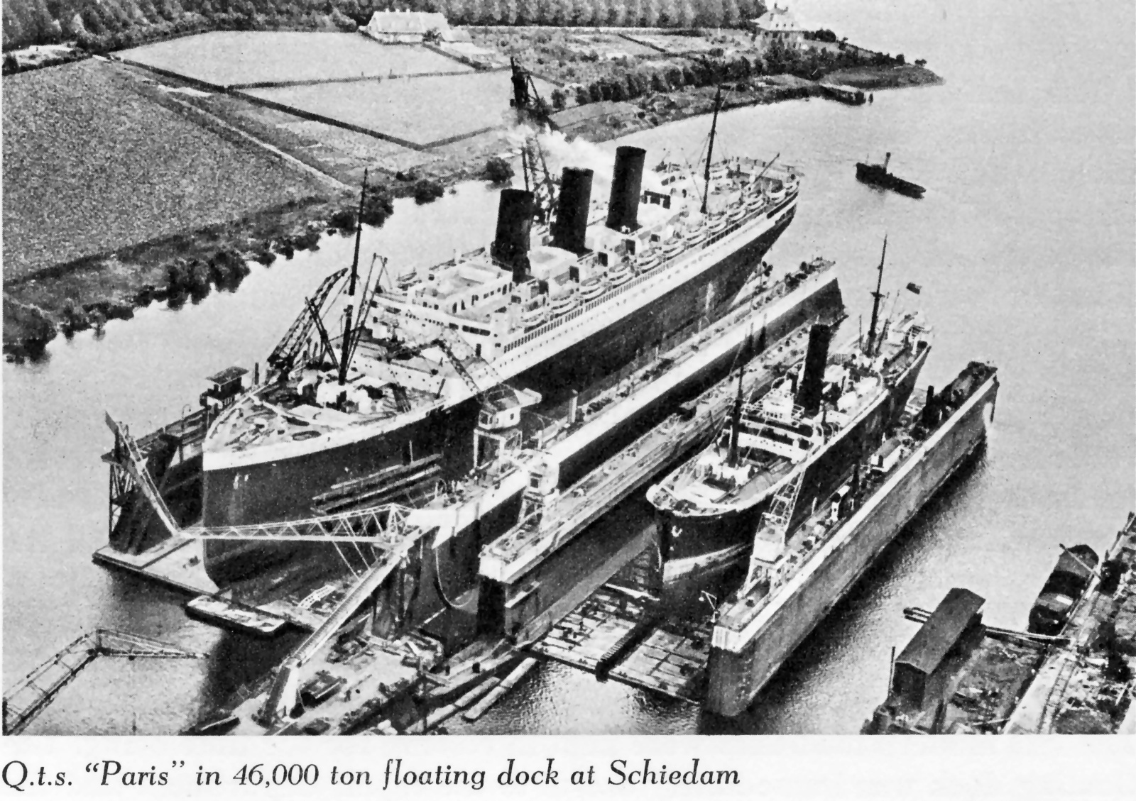
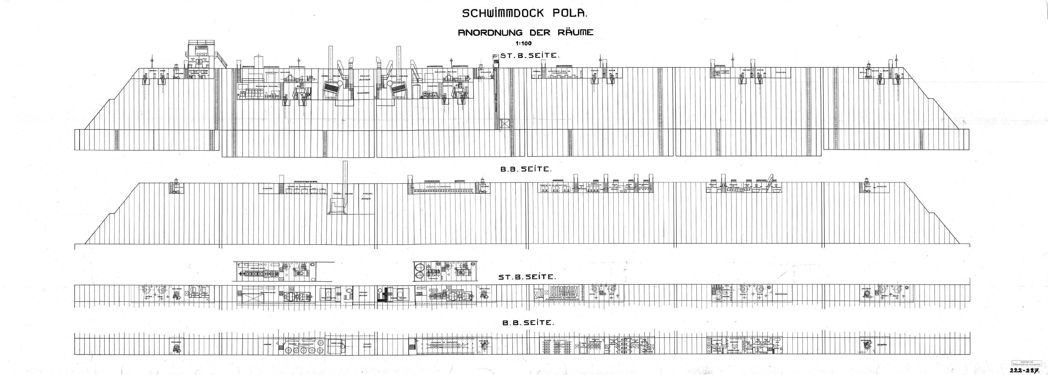
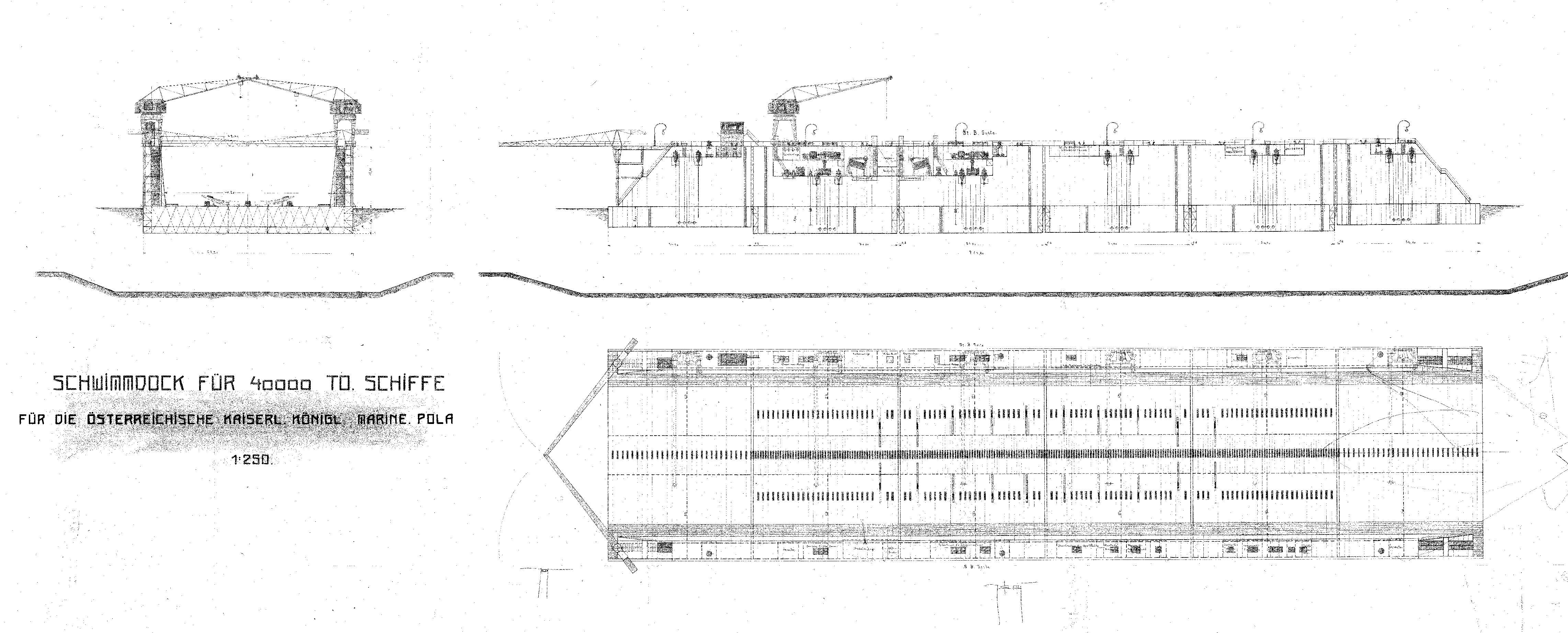
Drydocks
Dock 22
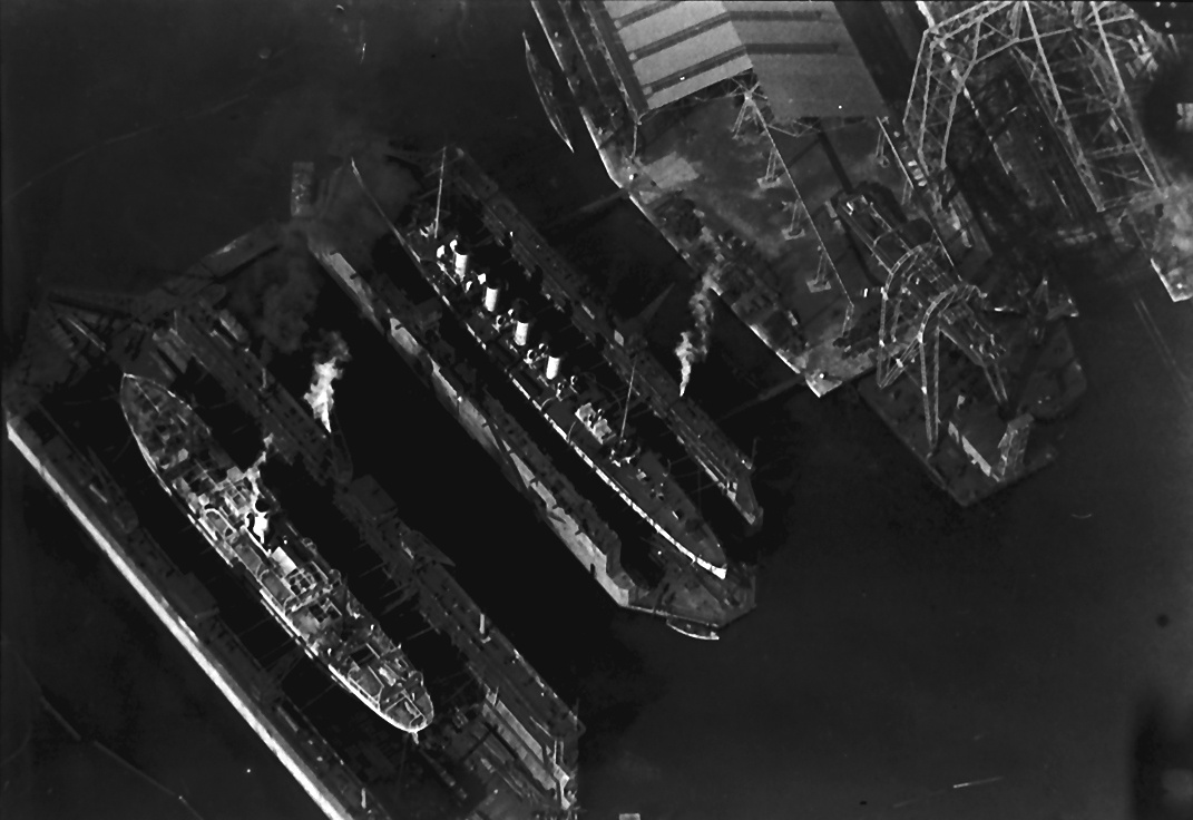
Dock 40